| |
Intrinsic Camera Calibration (work in progress)
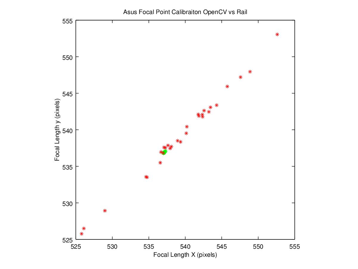
Description: This tutorial shows how to use the intrinsic camera calibration package to compute the camera intrinsic parameters using a rail guide and calibration target. The procedure uses a slightly different cost function than OpenCV and Matlab. It relies on knowing the distance the camera is moved between successive images. When performed precisely, the routine is both quicker because it requires fewer images and more accurate because the parameters have lower co-variance.Tutorial Level: INTERMEDIATE
Motivation
While a camera_calibration method does already exist, for some industrial and high precision applications, the results may not be sufficient. Depending on the number and quality of the images collected by the user, the calibration method can result in widely varying focal length values.

A 1-2% error in the focal length calculation could lead to a position error of ~2cm or more. Such position error could lead to problems if the robotic system is not designed to compensate for the error. Grippers could miss grasping parts or run into the part they are trying to grab. The rest of this tutorial will walk you through the steps for running the intrinsic rail calibration routine.
Requirements
ASUS PrimeSense camera
- Linear guide rail
- Calibration target
- When choosing a calibration target, keep in mind that we are using openCV's findCirclesGrid() routine. More circles means more measurements and therefore better results. However they can't be too small, or findCirclesGrid() won't find them at the far end of the rail.
- Incandescent lamp
Setup
- Place calibration target on a flat wall
- Setup calibration rail in front of the calibration target and ensure that the rail moves the camera back and forth along the z-axis of the camera as follows.

- Make sure that calibration target fills the field of view when camera is at the front most position.
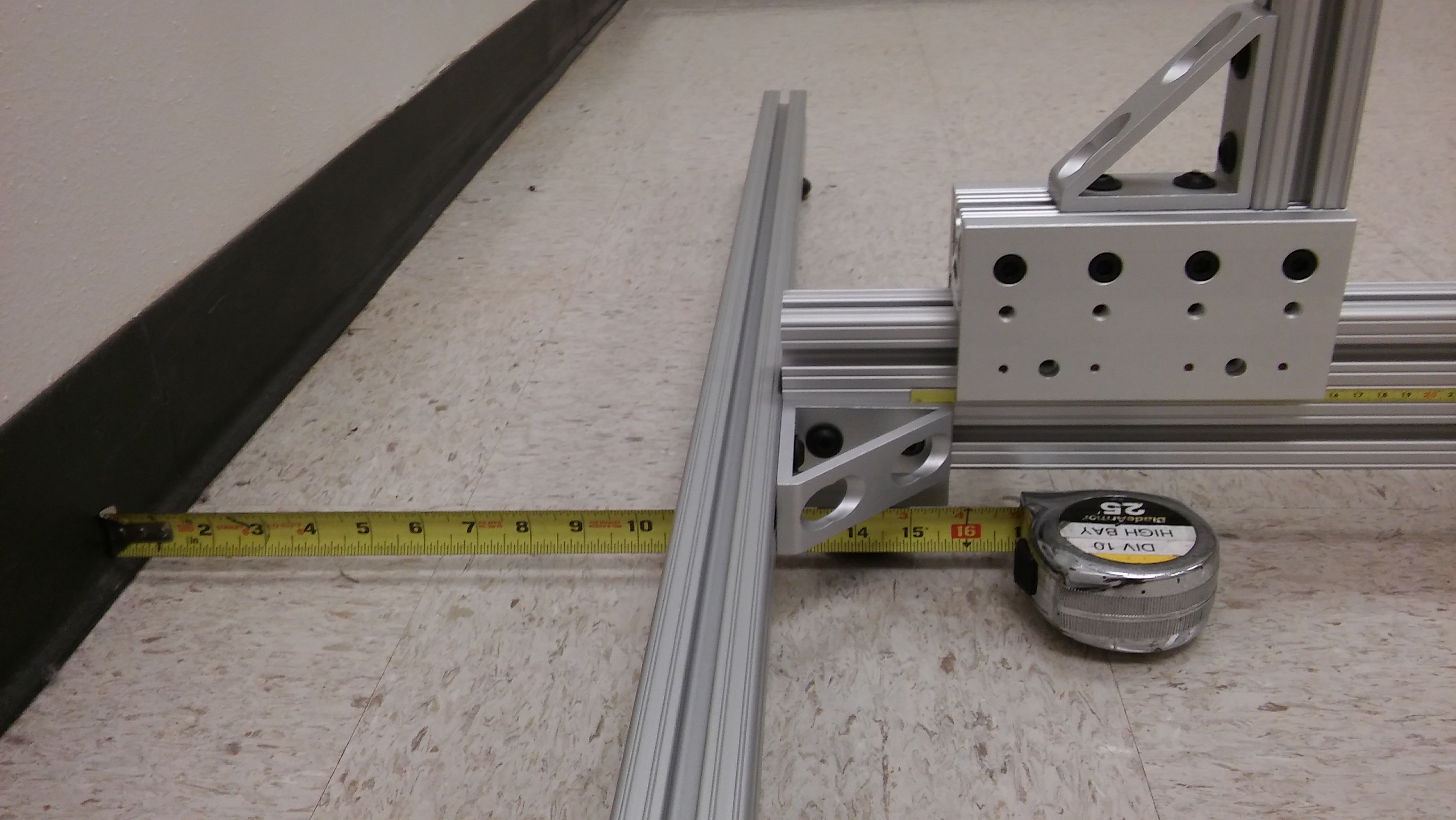
- Measure distance from the wall to the camera stand when it is at the front most position on the rail.

Run the program: roslaunch intrinsic_calibration rail_cal.launch. Slide camera to back position. Make sure that center pixel of image points at the same location in both the near and far locations. This ensures that the camera is pointing in the direction of travel of the rail. Adjust the camera pitch and yaw until the center pixel is the same, or very close, for both locations. This can be done by using the red circle drawn in the center of the image. Make sure that the pixel that shows up inside this circle is close to the same (within 1-5 pixels distance) in the near and far locations.


- Modify the launch file “rail_ical_asus.launch” to include the following (all lengths in are meters):
- The size of the calibration grid used (rows, columns, circle diameter, circle spacing)
- Rows/columns are determined based upon the location of the origin circle, which is located in the bottom left corner of the target.
- The distance of the camera from the calibration target when in the nearest location (measured in Step 2ii). This provides an initial condition for the one exterior pose estimated during calibration.
- The distance the camera moves at each increment
- The number of times the camera will be moved and a new image acquired (Should not exceed the travel of the rail)
- The size of the calibration grid used (rows, columns, circle diameter, circle spacing)
Procedure
roslaunch intrinsic_calibration rail_cal.launch
- Call service to start the process
rosservice call /RailCalService “allowable_cost_per_observation: 0.0”
- Set the cost per observation to a reasonable number. If the position measurement accuracy is within 1mm for each position, then the error is typically less than 1 pixel for each circle observed. If there is side to side wobble in your setup, you may observe more residual error. It should never be more than a few pixels.
- Move rail to the first/closest position where the target fills the field of view completely.
- Accuracy of rail placement affects the intrinsic calibration results. Be sure to measure accurately or use hard stops to ensure that the calibration is reliable.
- To capture each calibration image, set the ROS parameter “/rail_intrinsic_calibration/camera_ready” to true
- rosparam set /rail_intrinsic_calibration/camera_ready true
- Verify that the target was found correctly. All circles should have a white dot in the center, the origin circle should have a larger dot, and the top row should be connected with a white line.

- Move the rail to the next position as prompted in the terminal. Set the "camera_ready" parameter to true and repeat until all positions are completed.
- If the target was not found in any of the positions, resolve any issues and rerun the program. Depending on the size of your circle grid, there will be an upper limit on the distance away at which the target can be seen and identified. Possible causes of failure may include:
- Not enough contrast between circles and background, increase color contrast or lighting. Remove any glare that may exist on the target
- Improper circle spacing/sizing resulting in failed detections at far away distances. Make sure that distance between circles (especially the origin circle) is large enough that they can be distinguished in the image at all distances.
- Circles not being found at the edge of the field of view if the camera is too close to the target
- Repeat procedure for the IR camera
roslaunch intrinsic_calibration rail_cal.launch ir:=true
- Use an IR light source (incandescent light bulb) and cover up the IR projector or use a diffusor on the IR projector (can result in uneven lighting on target, too bright up close and too dim far away)
- Repeat steps 3-5
- Note that the results are stored by the camera's camera_info_manager


