Author: Alessandro Di Fava < alessandro.difava@pal-robotics.com >
Maintainer: Jordi Pages < jordi.pages@pal-robotics.com >
Support: tiago-support@pal-robotics.com
Source: https://github.com/pal-robotics/tiago_dual_tutorials.git
| |
Localization and path planning
Description: Learn how to run laser-based localization and autonomous navigation avoiding obstacles by means of global and local path planning.Keywords: Localization, amcl, path planning, autonomous navigation
Tutorial Level: INTERMEDIATE
Contents
Purpose
This tutorial shows how to make TIAGo++ navigate autonomously provided a map build up of laser scans and taking into account the laser and the RGBD camera in order to avoid obstacles.
The navigation that is shown in this tutorial is the basic navigation, an advanced navigation addon is available when purchasing a robot. This addon includes the creation of Zones of Interest, Virtual Obstacles and Points of Interest in the map. Additionally, it is using the RGBD camera of TIAGo ++ to detect obstacles not fully detected by only the 2D laser, like tables
Pre-Requisites
First make sure that the tutorials are properly installed along with the TIAGo++ simulation, as shown in the Tutorials Installation Section. Then, follow the instructions in the Create a map with gmapping tutorial in order to create and save a map.
Execution
First of all open two consoles and source TIAGo++'s public simulation workspace in each one
cd /tiago_dual_public_ws
source ./devel/setup.bash
In the first console launch the simulation of TIAGo with all the required nodes for running the autonomous navigation
roslaunch tiago_dual_2dnav_gazebo tiago_dual_navigation.launch public_sim:=true lost:=true
Alternatively, you can launch the simulation with the TIAGo OMNI ++ with the base_type parameter set to omni_base, by default this parameter is set to pmb2 :
roslaunch tiago_dual_2dnav_gazebo tiago_dual_navigation.launch public_sim:=true lost:=true base_type:=omni_base
The default map will be launched; if you want to run a specific map that you created you could run it with the map option and the path to your map folder :
roslaunch tiago_dual_2dnav_gazebo tiago_dual_navigation.launch public_sim:=true lost:=true map:=$HOME/.pal/tiago_dual_maps/configurations/<the_map_folder>
By default the /home/<your_username>/.pal/tiago_dual_maps/config folder is pointing to the latest saved map
Among other, the following information is overlaid on top of the map:
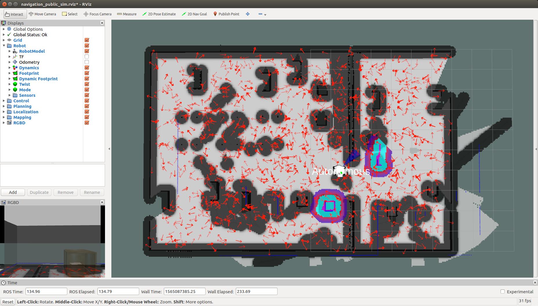
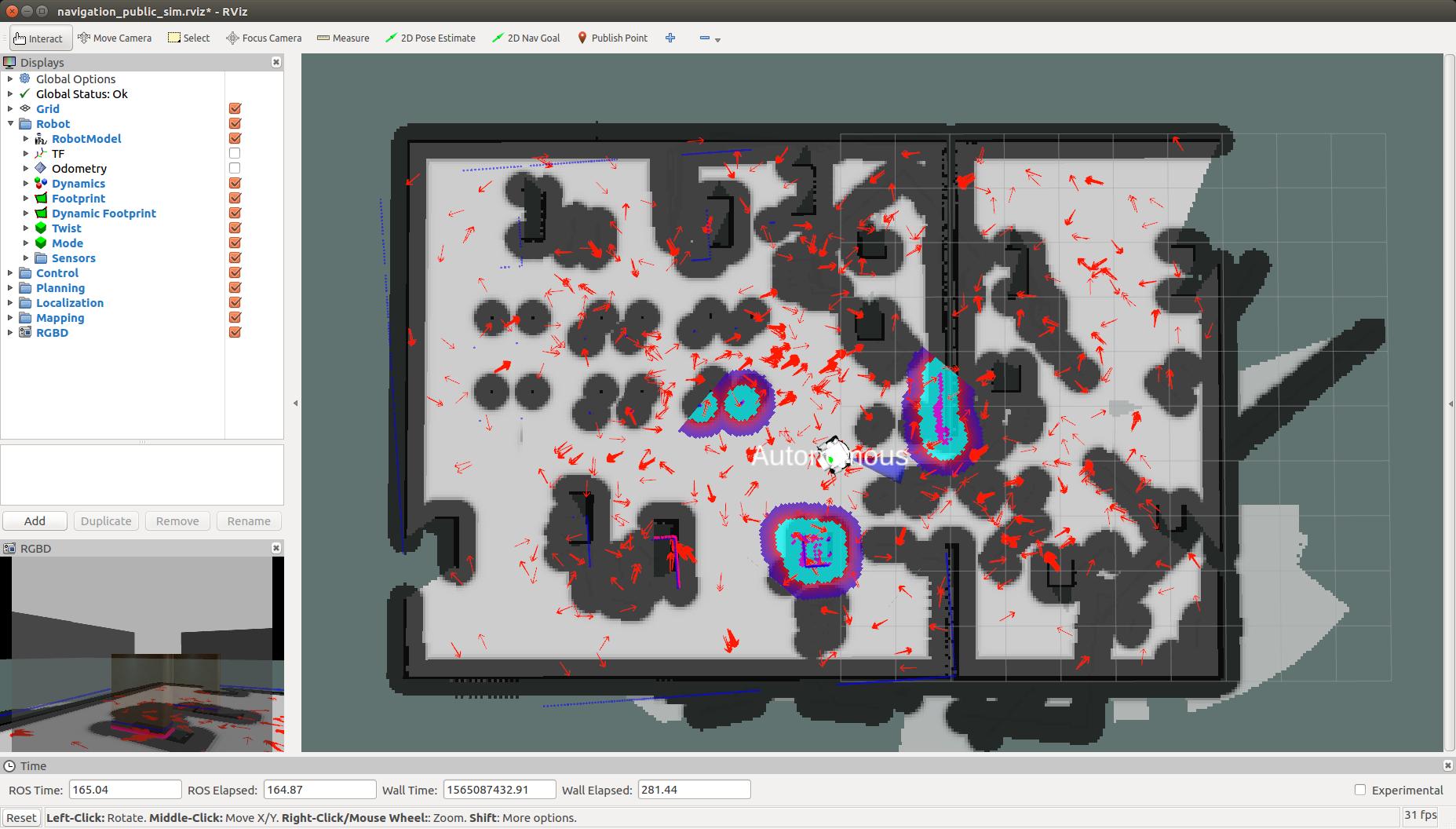
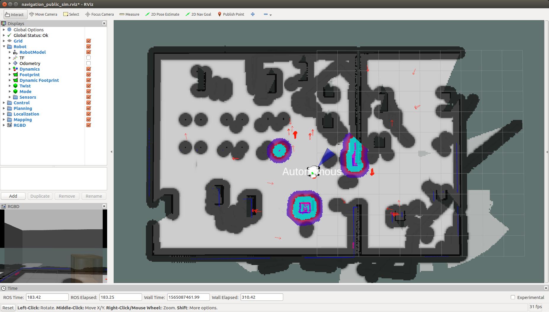
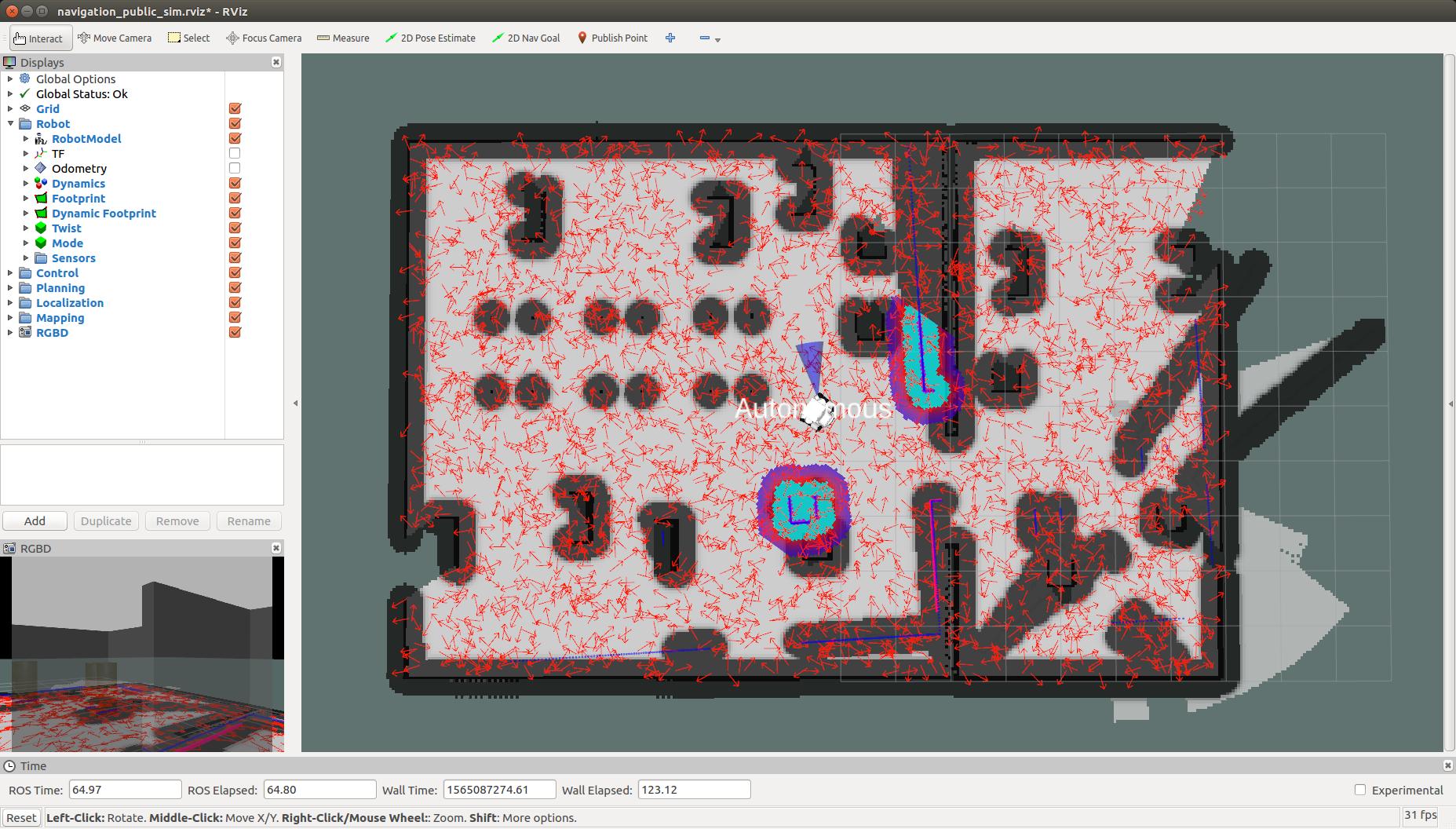
Particle cloud: a cloud of small red arrows representing the amcl filter particles, which spreads around the robot. A concentration of the particles indicates a growing confidence on its position estimate.
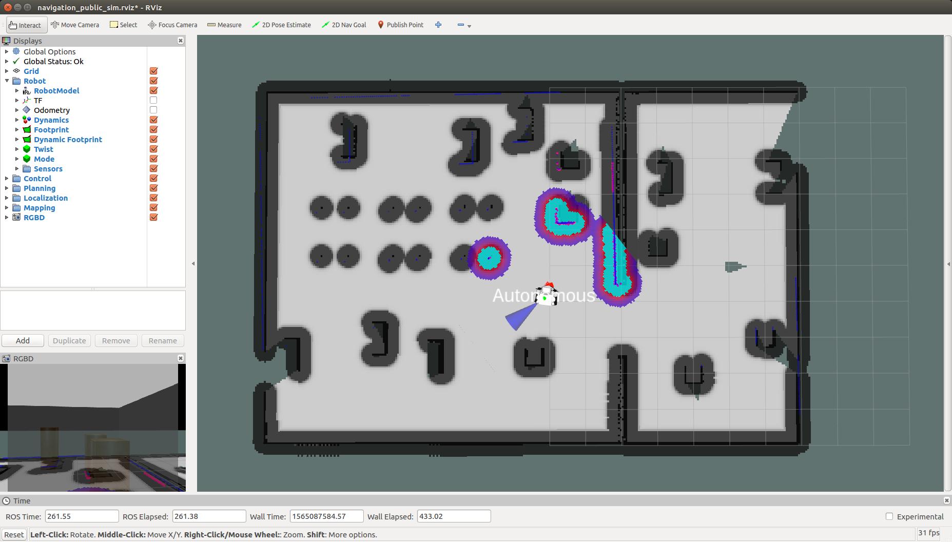
Global costmap: regions around obstacles which are used by the global planner in order to compute paths to navigate from one point of the map to another without getting too close to the static obstacles registered during mapping. More details can be found here: http://wiki.ros.org/costmap_2d
Local costmap: similar to the global costmap, but it is smaller and moves with the robot, it is used to take into account new features that were not present in the original map. It is used by the local planner to avoid obstacles, both static and dynamic, while trying to follow the global path computed by the global planner. More details can be found here: http://wiki.ros.org/costmap_2d
Laser scan: lines in dark blue represent the points measured with the laser of the mobile base. This scan is used to add/remove obstacles both in the global and local costmaps.
RGBD scan: lines in magenta represent the projection of the point cloud reconstructed by the RGBD camera of the head onto the floor. This artificial scan is also used to add/remove obstacles to the global and local costmaps. This scan is useful to obtain a 3D information of the environment, detecting obstacles that are higher or lower than the laser scanner plan.
Localization
As can be seen in the pictures below the robot wakes up in a position of the world which does not correspond to the map origin, which is the pose where the localization system assumes the robot is and where particles are spread representing possible poses of the robot.
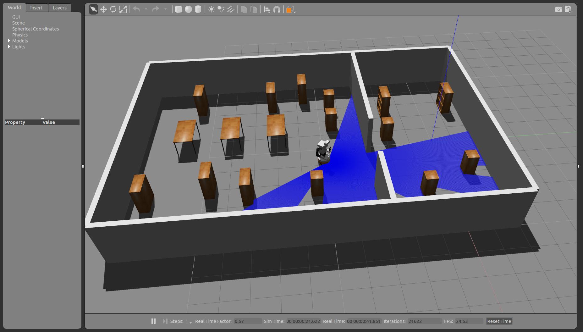
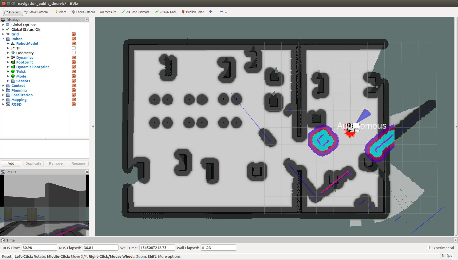
In order to localize the robot run the following instruction in the second console:
rosservice call /global_localization "{}"
This causes the amcl probabilistic localization system to spread particles all over the map as shown in the picture below.
Now a good way to help the particle filter to converge to the right pose estimate is to move the robot. A safe way to do so is to make the robot rotate about itself. You may use the left and right arrows of the key_teleop in order to do so.
rosrun key_teleop key_teleop.py
The result is shown in the following pictures, where invalid particles are removed as more laser scans can be matched with the map and the localization converges eventually to the correct pose.
|
|
|
|
Now, it is preferable to clear the costmaps as it contains erroneous data due to the bad localization of the robot:
rosservice call /move_base/clear_costmaps "{}"
The costmap now only takes into account obstacles in the static map and the system is ready to perform navigation.
Autonomous navigation with rviz and TIAGo ++
First of all make sure to kill the key_teleop node. Otherwise the robot will not move autonomously as key_teleop takes higher priority.
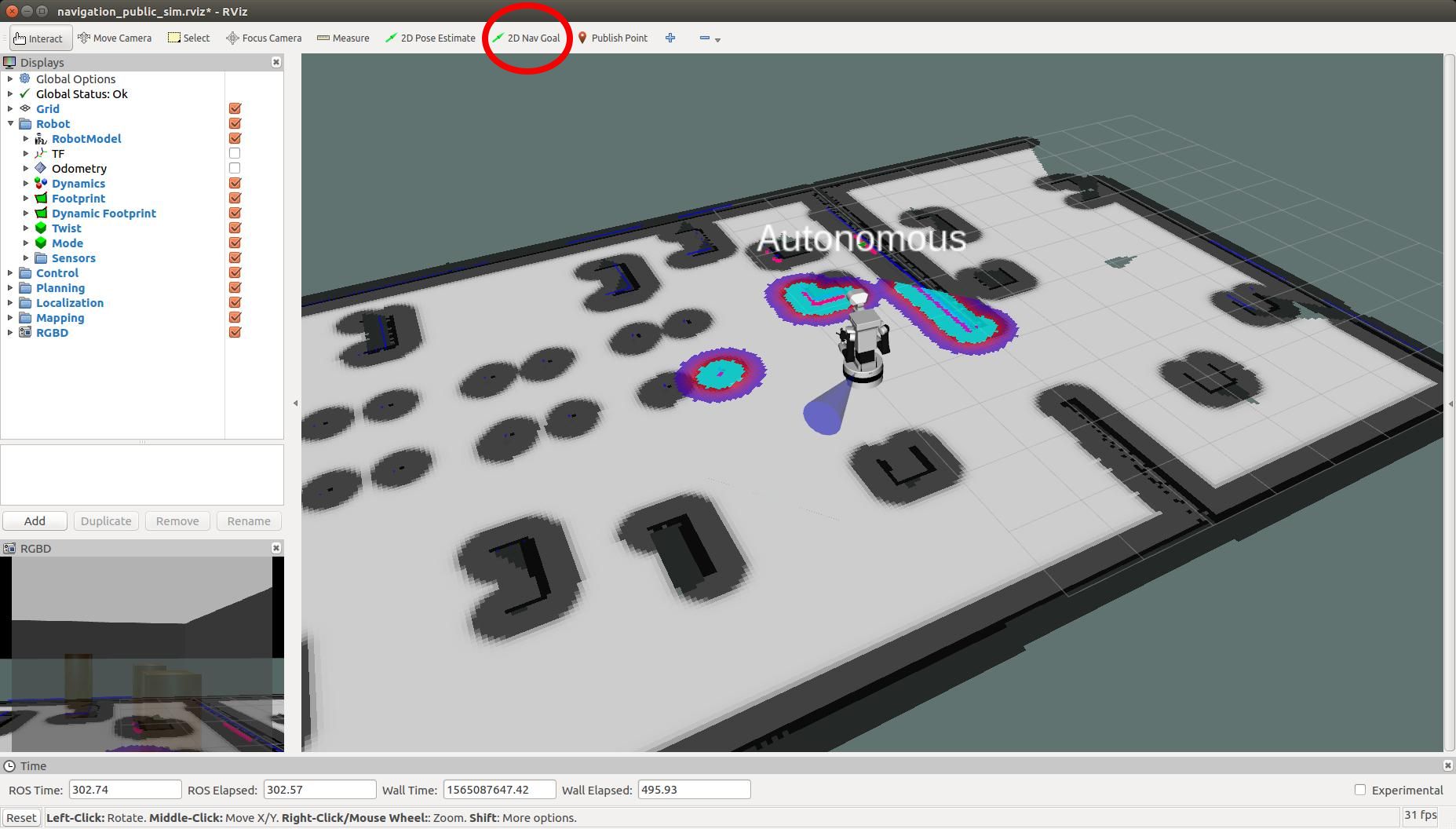
In order to send the robot to another location of the map the button 2D Nav Goal can be pressed in rviz.
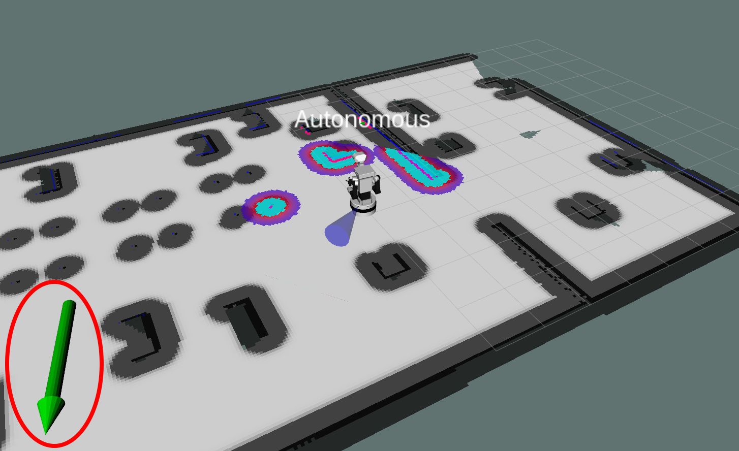
Then, by clicking and holding the left button of the mouse over the point of the map at which we want to send the robot a green arrow will appear. By dragging the mouse around the point the orientation will change. This arrow represents the target position and orientation that the robot needs to reach.
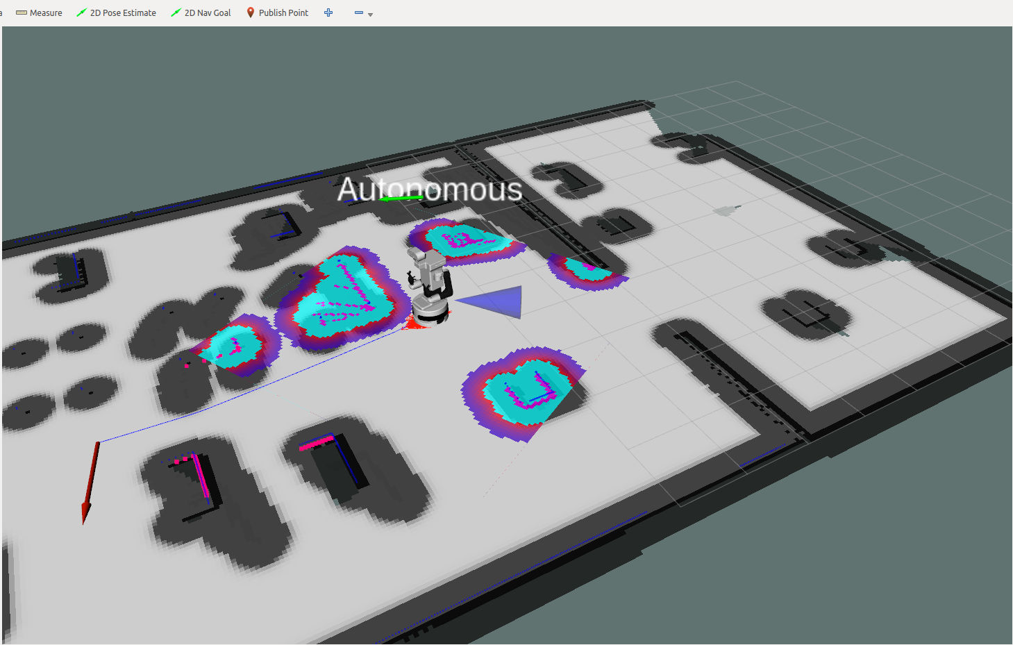
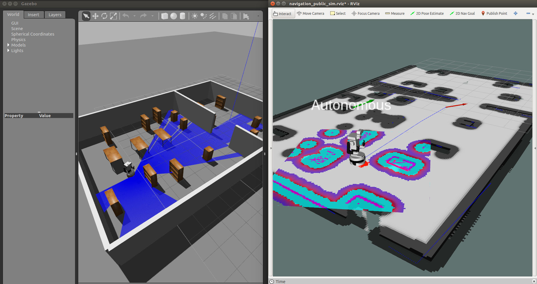
When releasing the mouse button the global planner will compute a path, which will appear as a blue line starting at the current position of the robot and ending with a red arrow representing the desired target orientation.
Then, the robot will start moving following the trajectory, which will automatically re-arrange when getting too close to unexpected obstacles. The pictures below show different snapshots of rviz and gazebo during the navigation toward the selected goal.
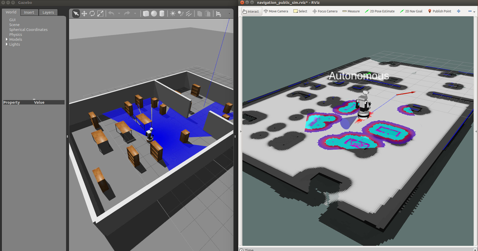
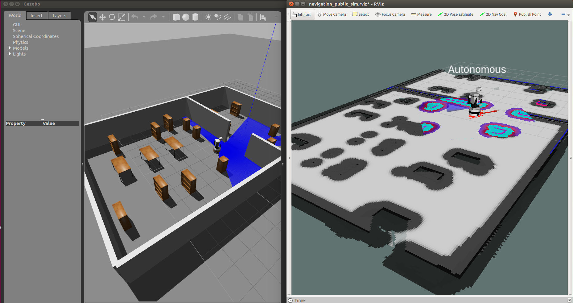
Finally, the robot stops when the target goal pose have been reached up to a user-defined tolerance.
Autonomous navigation with rviz and TIAGo OMNI ++
After launching the simulation for the TIAGo OMNI ++ you would have the same interaction with the button 2D Nav Goal as with the pmb2 as shown above; however the local planner is different.
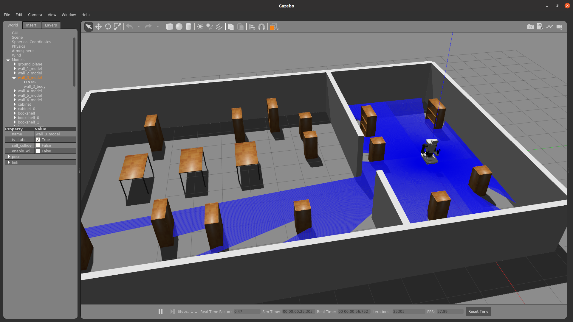
The robot will start moving following the global trajectory. Given the flexibility and the freedom that the TIAGo OMNI provides, an appropriate Local Planner has to be used in order to exploit all the degrees of freedom of the base and plan trajectories in the plane in each direction and orientation. For this purpose, a special configuration of the teb_local_planner has been used to follow the path of a Global Planner while avoiding obstacles in a flexible way, by considering the kinematics model of the omnidirectional base.
The pictures below show rviz during the navigation toward the selected goal.
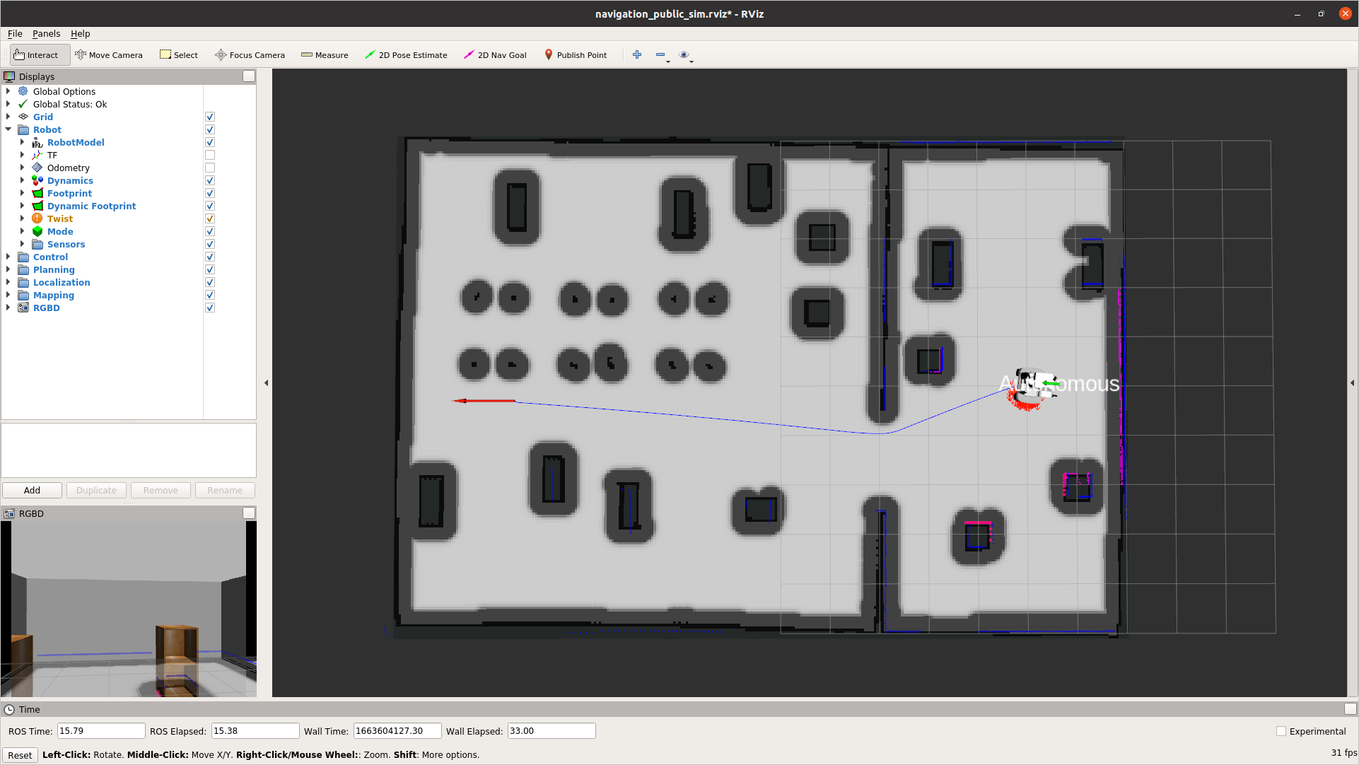
Finally, the robot stops when the target goal pose has been reached up to a user-defined tolerance.


