| Note: This tutorial will only work with the Electric distribution of ROS, and is experimental so may change.. This tutorial assumes that you have completed the previous tutorials: Planning Description Configuration Wizard. |
| |
Warehouse Viewer
Description: Learn to use the planning scene warehouse viewer, a GUI application for editing, loading, and saving planning scenes and trajectories.Keywords: arm navigation warehouse viewer gui trajectory planning electric
Tutorial Level: ADVANCED
Contents
Introduction
The planning scene warehouse viewer is a GUI application you can use to interact with the arm navigation stack. With this application, you can create, edit, save, and load planning scenes, motion plan requests, and trajectories. In addition, this application can be run alongside robot applications, and can dynamically display new information relevant to arm navigation.
Prerequisites
To use the warehouse viewer, you must have the move_arm_warehouse package, currently housed in the arm_navigation_experimental stack. The dependencies of this package should be sufficient to run the warehouse viewer. In addition, you should have rviz and its dependencies installed. To use the warehouse viewer to its full extent, you should also have an inverse kinematics solver, a planner, and a trajectory filter for your robot.
Launching the Viewer
Launch files are provided for running the warehouse viewer and its dependencies. To launch the warehouse viewer on its own (without any of its dependencies), use
roslaunch move_arm_warehouse planning_scene_warehouse_viewer_only.launch
This will launch the GUI application without launching the mongo database or any planners, trajectory filters, or inverse kinematics solvers. In addition, robot-specific launch files are included for the warehouse viewer which will launch all of its dependencies.
Launching the Viewer for the PR2
Default launch files for the PR2 are distributed in move_arm_warehouse/launch:
planning_scene_warehouse_viewer_pr2.launch launches the warehouse viewer, the mongo database, an OMPL planner node, a trajectory filter node, and inverse kinematics nodes. This launch file is for use with a simulated PR2, but can also be run with no robot active in ROS at all.
planning_scene_warehouse_viewer_pr2_real.launch same as above, but uses nodes exclusive to the real robot.
If you plan on using real or simulated robot data, then the robot's trajectory action clients and perception nodes must be launched before the warehouse viewer can be used.
Launching the Viewer for Other Robots
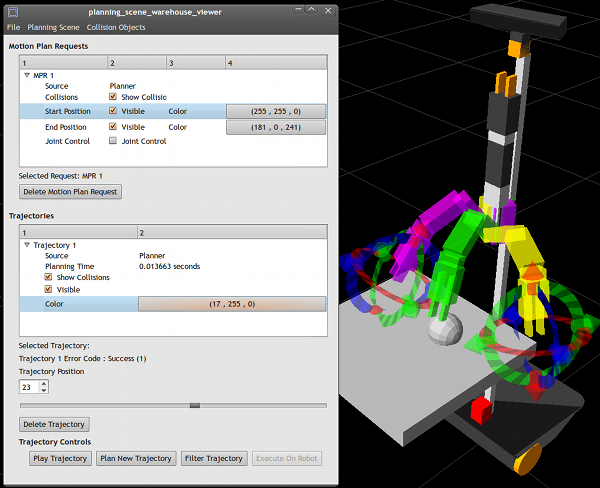
Figure 1: Warehouse Viewer running for Maxwell
The warehouse viewer supports other robots, provided that they have the following prerequisites:
Required Prerequisites
- Your robot must have at least one arm, but no more than two arms.
- Your robot must have a URDF file with collision models.
- You must have an inverse kinematics solver, planner, and trajectory filter for your robot.
Recommended Prerequisites
- Your robot should not have any multi-dof joints such as ball and socket joints. If your robot has one of these joints, joint control will not work properly.
- If you wish to execute trajectories on the robot, you must have a trajectory action client running which conforms to the arm_navigation interface.
Objects perceived by your robot must be added to the arm_navigation planning scene as CollisionObject or CollisionMap messages.
There are several parameters that must be set before the warehouse viewer can be used. These define the topics that your robot's planners, trajectory filters, and inverse kinematics solvers respond to. As an example, here is the complete list of robot-specific parameters given by the pr2 launch file. Any of these parameters can be ignored by entering "none" as the value of the parameter.
<!-- send parameters for multidof -->
<rosparam command="load" ns="robot_description_planning" file="$(find pr2_arm_navigation_config)/config/pr2_planning_description.yaml" />

<!-- Port to communicate with mongo db -- >
<param name="warehouse_port" value="27019"/>

<!-- Called when left arm executes trajectory using controllers -->
<param name="execute_left_trajectory" value="/l_arm_controller/follow_joint_trajectory" />

<!-- Called when right arm executes trajectory using controllers -->
<param name="execute_right_trajectory" value="/r_arm_controller/follow_joint_trajectory" />

<!-- Called to get left arm inverse kinematics with collision checking --> <param name="left_ik_name" value="/pr2_left_arm_kinematics/get_constraint_aware_ik" />

<!-- Called to get right arm inverse kinematics with collision checking --> <param name="right_ik_name" value="/pr2_right_arm_kinematics/get_constraint_aware_ik" />

<!-- Called to get left arm inverse kinematics without collision checking -->
<param name="non_coll_left_ik_name" value="/pr2_left_arm_kinematics/get_ik" />

<!-- Called to get right arm inverse kinematics without collision checking -->
<param name="non_coll_right_ik_name" value="/pr2_right_arm_kinematics/get_ik" />

<!-- Kinematic chain group name representing the left arm -->
<param name="left_arm_group" value="left_arm" />

<!-- Kinematic chain group name representing the right arm -->
<param name="right_arm_group" value="right_arm" />

<!-- Degree of freedom representing inverse kinematics redundancy on the left arm -->
<param name="left_redundancy" value="l_upper_arm_roll_joint" />
<!-- Degree of freedom representing inverse kinematics redundancy on the right arm -->
<param name="right_redundancy" value="r_upper_arm_roll_joint" />

<!-- Link on the left arm to perform inverse kinematics for -->
<param name="left_ik_link" value="l_wrist_roll_link" />

<!-- Link on the right arm to perform inverse kinematics for -->
<param name="right_ik_link" value="r_wrist_roll_link" />

<!-- Called to plan trajectories given motion plan requests -->
<param name="planner_service_name" value="/ompl_planning/plan_kinematic_path" /

<!-- Interpolates between end effector positions for the left arm -->
<param name="left_interpolate_service_name" value="/l_interpolated_ik_motion_plan" />

<!-- Interpolates between end effector positions for the right arm --> <param name="right_interpolate_service_name" value="/r_interpolated_ik_motion_plan" />

<!-- Called to smooth and optimize a planner trajectory -->
<param name="trajectory_filter_service_name" value="/trajectory_filter/filter_trajectory_with_constraints" />
From the Planning Description Configuration Wizard
If, however, your robot planning description was made using the planning description configuration wizard, you can bypass all of this by typing the following:
roscd move_arm_warehouse;
./scripts/create_launch_files.py <your_robot_name>
This will generate a launch file called planning_scene_warehouse_viewer_<your_robot_name>.launch in the launch directory of your <robot>_arm_navigation package. Then type the following:
roslaunch <your_robot_name>_arm_navigation
planning_scene_warehouse_viewer_<your_robot_name>.launch
This will launch the planning scene viewer and all of its dependencies for your robot.
Rviz Setup
Rviz should be running alongside the warehouse viewer. To properly set up rviz to display and interact with the contents of the warehouse viewer, your rviz setup should look something like this:
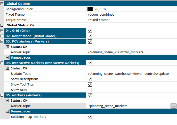
Figure 2. Rviz Properties
One interactive marker topic /planning_scene_warehouse_viewer_controls/update must be subscribed to, as well as two static marker topics, /planning_scene_markers, and /planning_scene_visualizer markers. These are for collision objects, and arm links, respectively.
Also, make sure that you have the "Interact" tool selected, and that the base frame of Rviz is correct for your robot.
Using the Viewer
The warehouse viewer is GUI program designed to be run alongside Rviz. If you are familiar with the planning components visualizer, then you might recognize that the warehouse viewer is very similar to it (albeit much more complex).
Parameters
When you begin the warehouse viewer, you will be shown a parameter dialog where you can verify and edit the ROS parameters passed in to the warehouse viewer.Here is the parameter dialog with the default (PR2 specific) parameters in place.
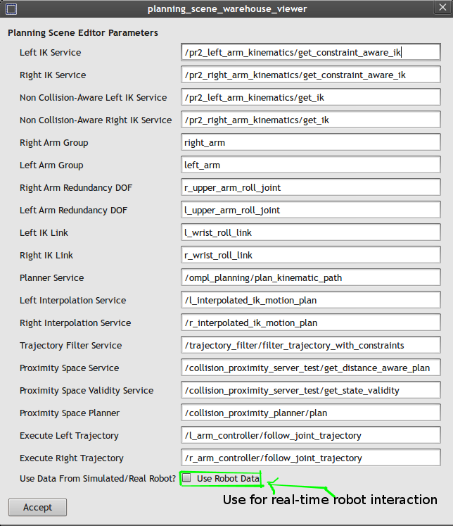
Figure 3. Parameter Dialog
These parameters are passed in as ROS params to the dialog, but they can be verified and edited by the parameter dialog before the viewer runs. Any of these parameters can be ignored by typing "none" into the field listed. In addition, the checkbox labeled "Use Robot Data," when checked, will allow you to send commands to the robot via the Execute Left Trajectory and Execute Right Trajectory parameters, and record the resulting trajectories. Press "Accept" when you are satisfied with the listed parameters.
Warning: Do not check "Use Robot Data" while the Execute Left Trajectory and Execute Right Trajectory services are not being advertised. Make sure they are running by invoking rosservice. Otherwise, the viewer will hang on startup while waiting for these (or any other) services.
Components of the Viewer
After you've accepted the parameter list, the warehouse viewer will subscribe to the requested topics, and the following window will appear:
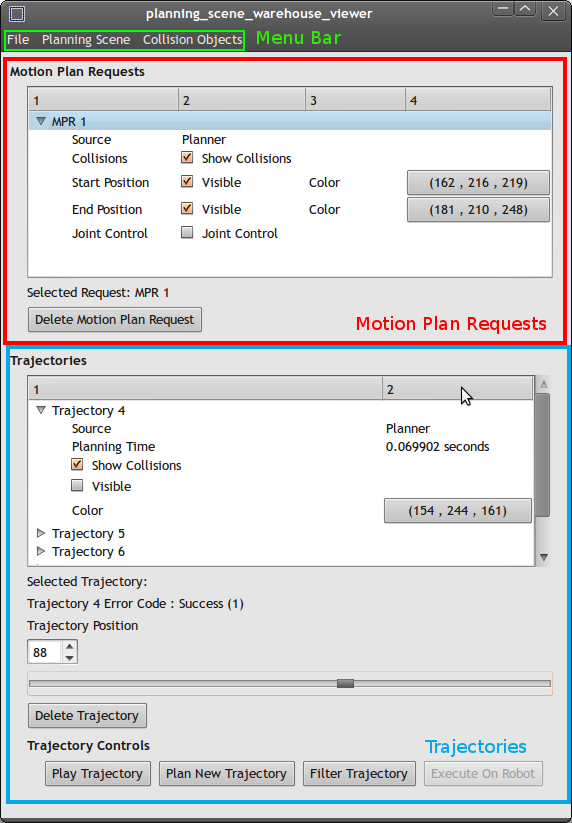
Figure 4. Main Window
This is the main window of the warehouse viewer. The rest of this tutorial will refer to the menu bar, the motion plan request box, and the trajectory box, which are labeled here for your convenience. When you first open the viewer, the motion plan box and the trajectory box will both be empty. As motion plan requests are created, they will appear in the motion plan box.
Click on the name of a motion plan request (which should be "MPR 1", "MPR 2", etc .) to select it. The selected request name will appear near the bottom of the motion plan request box. In the image above, the selected request is "MPR 1." At any time, you can delete the selected request by pressing the "Delete Motion Plan Request" button.
After you have selected a motion plan request, all of the trajectories associated with that request will appear in the trajectory box below. You can select trajectories in the same way as you select motion plan requests, and can delete them as well. Deleting a motion plan request will also delete each of its trajectories.
Planning Scenes
Planning Scenes are the bread and butter of the arm navigation system in ROS. A Planning scene consists of the robot and its current state, the collision objects in the environment, motion plan requests within that planning scene, and trajectories associated with each motion plan request. The planning scene exists to tell planners and collision-aware inverse kinematics solvers what obstacles to avoid, and to provide a method of validating robot states and trajectories to ensure that they are collision-free.
When using the warehouse viewer, you will interact with a single planning scene. You can edit the motion plan requests, trajectories, and collision objects associated with that scene, and then save the scene to a MongoDB database.
Upon starting, the warehouse viewer will create an empty planning scene for you to edit. An empty planning scene consists of the robot in its default state (specified by the URDF if you are not using robot data, or the robot's current joint state if you are using robot data), and a world free of collision objects.
You can make a new planning scene at any time by using the menu command:
File > New Planning Scene ...
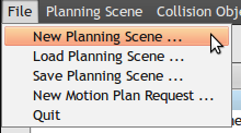
This will prompt you to save the current planning scene before creating a new, (empty) one.
To view the state of the current planning scene, and to refresh it, open the "Planning Scene" menu on the menu bar.

Outcomes
An Outcome is an error code associated with a particular feature of the planning scene. For instance, each trajectory in the planning scene is associated with a particular error code such as Success, Planning Failed, Collision Constraints Violated, etc. In addition, each Pipeline Stage is associated with an error code. A Pipeline Stage is an arbitrary name defined by the application using the arm navigation stack. For example, the move_arm_simple_action program has several pipeline stages, such as "before ik", "after ik", "planner", "filter", "monitor", and so on.
You can view the outcomes associated with a planning scene by going to the menu
Planning Scene > View Outcomes ...
When you do this, the following modal dialog will appear:
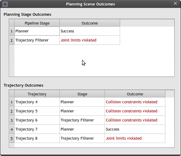
Figure 5. Outcome Table
The outcome dialog has two parts: the planning stage outcomes table, and the trajectory outcomes table. In the dialog shown, the planning stage was successful, but the trajectory filter violated the robot's joint limits. Further details are given by the trajectory outcome dialog. Trajectories 4, 5, and 6 were unsuccessful due to collisions with the environment. This can happen when the robot sees obstacles in the environment which collide with planned trajectories. Trajectory 7 was successful, but Trajectory 8, which was produced by the trajectory filterer, violated the robot's joint limits.To see where an error occurred, mouse over the error in the trajectory outcomes table, and a tool tip will appear showing you which trajectory point contained the error.
All error codes except for Success are shown in red.
Refreshing
During execution, other programs (such as the robot head monitor) may make changes to the planning scene stored on the arm navigation environment server. To reflect these changes in the planning scene warehouse viewer, you may refresh the planning scene by going to the menu
Planning Scene > Refresh Planning Scene ...
Collision Objects
Collision Objects consist of polyhedral obstacles in the planning environment which planners and collision-aware IK solvers must avoid. These can be simple geometric shapes such as boxes, spheres and cylinders, or they can be collision maps (which are collections of voxels) generated by point clouds, or even imported meshes. The planning scene warehouse viewer allows you to create and manipulate simple geometric collision objects.
(Note: currently, collision maps and meshes are not interactive in the warehouse viewer, but they can be loaded from existing planning scenes or imported by other programs)
Creating Collision Objects
To create a collision object, go to the menu
Collision Objects > New Collision Object ...

Then, the following dialog will appear:
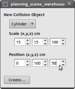
Figure 6. Collision Object Dialog
Using this dialog, you can create boxes, cylinders and spheres of various sizes. For boxes, the sizes given in centimeters correspond to the x, y and z lengths of the box's sides. For cylinders, the first scale field corresponds to the radius of the cylinder, the second field is ignored, and the third field is the height of the cylinder. For spheres, the first scale field is the radius of the sphere, and the other two are ignored.
The position fields correspond to an arbitrary point in 3D space in centimeters. These positions can be negative.
Press "Create ..." to place the collision object in the planning scene. It will then appear as an interactive marker in rviz.
Posing Collision Objects
After creating the collision object from the above example, a simple pole should appear in RVIZ as an interactive marker. Make sure the "Interact" tool is selected as the active tool in RVIZ. You can select the pole by either left clicking on it, or right clicking and pressing "Select." The pole can also be deleted at any time by right clicking on it and pressing "Delete."
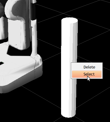
Figure 7. Selecting a Collision Pole
After you have selected it, a set of 6DOF controllers will be created around it. The arrow controls represent motion along a set of axes relative to the object's 6DOF pose, while the rings represent rotation around these axes. Pose the pole as desired, and deselect it by right clicking on it and pressing "Deselect."
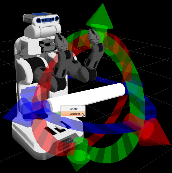
Figure 8. Posing a Collision Pole
Complex planning scenes can be created in this manner out of simple shapes.
Motion Plan Requests
A Motion Plan Request is a ROS message that specifies start constraints and goal constraints. They are used to specify the command "Get from the start state to the goal state without hitting anything in the planning environment" for the robot. A constraint may be a set of joint angles, a 6DOF pose, or other specifications. Arm planners take in motion plan requests as input, and generate trajectories from the start constraints to the goal constraints as output. Inverse kinematics solvers take position constraints on the start and goal of a motion plan request to generate a set of joint angles.
Currently, the warehouse viewer only supports joint constraints on the start and goal of a motion plan request. That is, the start state of a motion plan request corresponds to the robot's current joint positions, and the goal state of a motion plan request corresponds to an arbitrary set of joint positions that the robot must plan to.
To create a motion plan request, go to the menu
File > New Motion Plan Request ...

Then, the following window will appear:
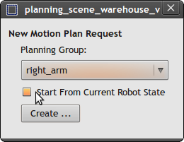
Figure 9. Creating a Motion Plan Request
There are two options provided, first, the planning group (which for the PR2 is either the right arm or left arm) that the motion plan request should be performed for, and second, whether the motion plan request should begin from the current robot state. If the check box "Start From Current Robot State" is checked, then the motion plan request will ignore its start state, and use the robot's current state as the start state instead. This should be used when interacting with an actual robot while the warehouse viewer is active.
Press "Create ..." to add the motion plan request to the planning scene.
After creating the motion plan request, it will appear in the motion plan box as a new entry:
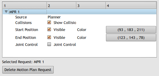
Figure 10. Motion Plan Request Box
The new motion plan request created was called "MPR 1." There are controls for its start position, end position, collisions, and joint control. You will also see in RVIZ that a new set of markers have appeared for interacting with the motion plan request, labelel "MPR1_start_control" and "MPR1_end_control."
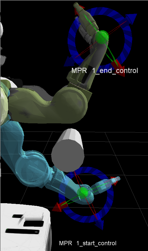
Figure 11. Motion Plan Controls
Here, I've moved the start position down below the pole, and the end position is the current state of the robot. You can turn either one of these on or off by toggling the "Visible" check box for the corresponding motion plan request.
IK Control
Over the start and end positions of the motion plan requests, you should see a 6DOF control. This represents the pose of the end effector of the robot. If you re-pose these using their 6DOF controls, the IK solver will attempt to produce a set of joint angles. The resulting robot state will be displayed as a set of colorful markers in RVIZ. If no IK solution can be found (for instance if the pose is in collision), then the end effector of the arm will appear to be disconnected, and the set of markers will turn to a bright red color:
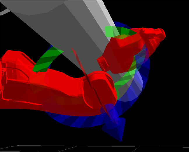
Figure 12. Bad IK Solution
In this state, the motion plan request has no valid joint constraints. If you wind up in a bad state, you can go back to the last good state, or go to a random joint state by right clicking one of the interactive IK controls and invoking a command from its menu:
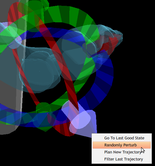
Figure 13. IK Control Menus
The menu entries are:
Go To Last Good State: Sets the pose of the end effector to the one which had the last good IK solution. If none exists, the pose will be set to the default state of the robot.
Randomly Perturb: Attempts to find a random set of joint angles that are not in collision. If no solution is found in 100 iterations, nothing happens.
Plan New Trajectory: Invokes the planner to plan from the start state to the end state of the motion plan request, producing a new trajectory and selecting it.
Filter Last Trajectory: Invokes the trajectory filterer on the currently selected trajectory, producing a new trajectory and selecting it.
Joint Control
In addition to using the IK solver to produce joint angles for the starting and ending positions of motion plan requests, you can also control the joint angles of the start and end positions of the request directly.To enable joint control, check the check box labeled "Joint Control Active" for the selected motion plan request. A new set of controls will appear in rviz:
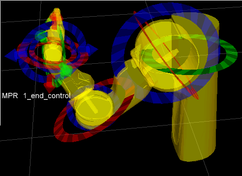
Figure 14. Joint Controls
Each of the ring controllers over the joints of your robot can be used to directly control the joints of your robot. Drag the ring controllers to move the joints. They will automatically obey joint limits, but can easily put the robot state into collision.
Collisions
If the "Show Collisions" check box has been checked for your motion plan request, then collisions with the planning scene will be shown as red spheres in RVIZ. Collisions will be shown not only for your planning group, but for the entire robot.
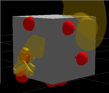
Figure 15. Collisions
The red spheres can be selected in RVIZ using the "select" tool. This will show which links exactly are colliding.
Colors
In addition, the start and end colors of the motion plan requests can be altered. By default, these are given random colors. The button with the 3-tuple corresponds to the red/green/blue values of markers' color. Click the button to produce a color dialog.
Trajectories
In the ROS arm navigation stack, trajectories are represented by a discrete set of robot states, and other corresponding information such as joint velocities. In the warehouse viewer, each motion plan request is associated with a set of trajectories. Trajectories can be produced from different sources such as motion planners, trajectory filterers, and from the robot monitor. The warehouse viewer provides several tools for producing and analyzing trajectories.
Planning
A planner's task is to take a motion plan request and produce a trajectory from it. By default, the warehouse viewer is set up to use the Open Motion Planning Library (OMPL) planner, which uses a randomized sampling based method to produce very fast (albeit jerky) results.
Once you are satisfied with the start and goal positions of your motion plan request, you can invoke a planner by either right clicking on the IK control of the motion plan request and pressing "Plan New Trajectory" or by pressing the "Plan New Trajectory" button on the planning scene warehouse viewer itself. After planning a new trajectory, the warehouse viewer will save the resulting trajectory, and it will appear in the trajectory box. If the plan fails, an empty trajectory will be saved to the trajectory box, and a relevant error code will be saved to the trajectory outcomes table.
Filtering
Many planners rely on a post-processing, or "filtering" stage to smooth the resulting planner trajectory and make it executable by an actual robot. Usually, these randomly interpolate collision-free cubic splines between random pairs of points in the trajectory, resulting in a much smoother, much slower trajectory with many more points. Trajectory filtering usually takes much longer than planning. While the OMPL planner may take a few milliseconds to produce a plan, the Trajectory filter can take up to two seconds to process the resulting planned trajectory.
To produce a filtered trajectory, either right click on the IK controller in RVIZ of the desired motion plan request and press "Filter Last Trajectory" or select a trajectory in the trajectory box of the warehouse viewer, and press the "Filter Trajectory" button. After a couple of seconds, a new trajectory will be saved to the trajectory box. If filtering failed, a relevant error code will be saved to the trajectory outcomes table.
Execution / Monitoring
When interacting with a real or simulated robot, you may also execute any trajectory on the robot, causing the robot's controllers to follow the trajectory. Before you do this, make sure the following prerequisites have been met:
- You must have pressed "Use Robot Data" at the starting parameter dialog.
- Your motion plan request must begin reasonably close to the robot's start state.
Your trajectory must have been filtered before execution. Do not attempt to execute raw OMPL plans, as you may easily damage your robot.
To execute a trajectory on the robot, select a trajectory from the trajectory box, and press the "Execute On Robot" button. Once you have done this, the robot will follow the trajectory, and the resulting executed trajectory will be saved to the trajectory box.
To do this, the warehouse viewer constantly monitors the robot's state, and records a discrete set of states observed during trajectory execution.
Playing Trajectories
Trajectories are displayed as an animated set of markers in RVIZ. By pressing "Play Trajectory," you can see the resulting trajectory as a moving set of markers in RVIZ. (Note: the trajectory is not displayed in real-time). In addition, you can drag around the slider below the trajectory box to see individual states of the trajectory. The spin box above the slider corresponds to the current trajectory point displayed in RVIZ.
Visibility
The markers for a trajectory can be turned on and off by checking the "Visible" check box for that trajectory.
Collisions
Just as with the motion plan requests, collisions with the current state of a trajectory can be visualized as red spheres in RVIZ by checking the "Show Collisions" check box for that trajectory.
Colors
Just as with motion plan requests, the colors of trajectories can be selected by clicking on the button with the 3-tuple representing red/green/blue color values for that trajectory.
Saving and Loading
Once you are satisfied with your planning scene, you can save it to the mongodb database. You may then load it later for further analysis. Any planning scene saved to the warehouse will be visible from the warehouse viewer.
Saving
To save your planning scene, simply choose the menu
File > Save Current Planning Scene ...

Your planning scene will be saved with the current time stamp. (Note: At this time, it is not possible to overwrite existing planning scenes.)
Loading
To load a planning scene, simply choose the menu
File > Load Planning Scene ...
This will bring up the load planning scenes dialog:
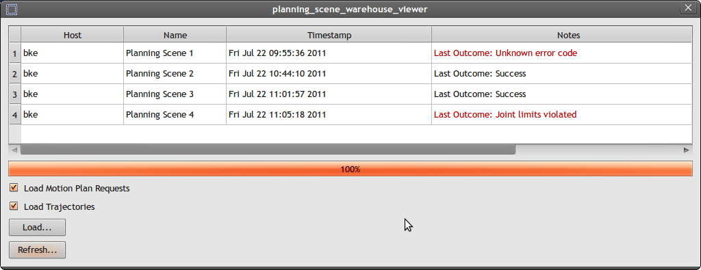
Figure 16. Load Planning Scene Dialog
This dialog represents the current state of the mongoDB database. The first column corresponds to the host name of the device that recorded the planning scene. In this example, "bke" was the name of the computer in the network that recorded the planning scene. The second column is an arbitrary ID uniquely defining the planning scene. (This is not saved in the database, but is only used by the warehouse to keep track of scenes). The third column corresponds with the time that the planning scene was recorded. The fourth and final column lists the final outcome recorded in the planning scene, as viewed in the planning scene outcomes dialog. All outcomes other than "Success" are recorded in red.
If you only wish to load the collision objects associated with a scene, you can choose to disable loading of trajectories and motion plan requests. Planning scenes can be made robot agnostic by choosing not to load motion plan requests or trajectories (which are robot specific).
You can refresh the database by pressing "Refresh ..." this will re-pull all of the planning scenes from the database.
To load a planning scene, click on its name, and then press "Load ..." this will prompt you to save the current planning scene.


