| |
Capturing Calibration Data.
Description: This tutorial will show you the complete process of gathering calibration data using the asr_mild_calibration_tool.Tutorial Level: BEGINNER
Contents
Setup
See asr_kinematic_chain_optimizer on how to use your calibration data gathered in this tutorial to calibrate your kinematic chain.
Prior to launching the calibration tool, make sure the following components are up and running:
Laserscanner
Depending on which laserscanner you want to use, set the parameter laserscanner_type in the calibration_tool_settings.yaml either to LMS400 or PLS101.
To launch the PLS101 scanner, you need to run.
roslaunch asr_mild_base_launch_files mild.launch
To use the LMS400 scanner, nothing has to be done since the communication will be handled by the calibration tool itself.
PTU
In order to move the camera during the automatic marker search, both the asr_flir_ptu_driver as well as the asr_flir_ptu_controller have to be running.
Start them by running
roslaunch asr_flir_ptu_driver ptu_left.launch
as well as
roslaunch asr_flir_ptu_controller ptu_controller.launch
Camera
Next, launch the camera system using
roslaunch asr_resources_for_vision guppy_head_full_mild.launch
AR-Marker-Recognition
Once the camera is running, the last step is to set up the AR-Marker-Recognition using
roslaunch asr_aruco_marker_recognition aruco_marker_recognition.launch
Tutorial
Now that all components are up and running, the calibration tool can be launched by using the command
asr_mild_calibration_tool calibration_tool.launch
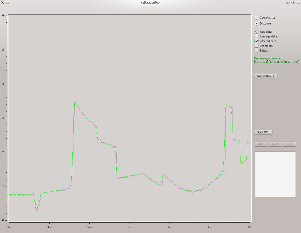
If everything has been set up correctly, the calibration tool should be visualizing the range data sent by the robot's laser scanner:
To get even more information about the gathered calibration data, you can visualize the current data using rviz:
rosrun rviz rviz -d $(rospack find asr_mild_calibration_tool)/doc/calibration.rviz
The tool should now already try to detect edges of the calibration object.
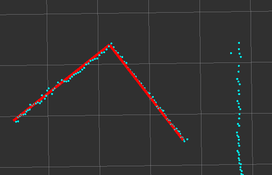
Once you see the calibration object's edges visualized in rviz or the calibration tool itself, press "Start Capture" to make the tool try to calculate possible object poses out of the current data.
If at least one possible solution for the current data has been found, the result will show up in the lower right corner of the calibration tool, as well as a visualization in rviz:
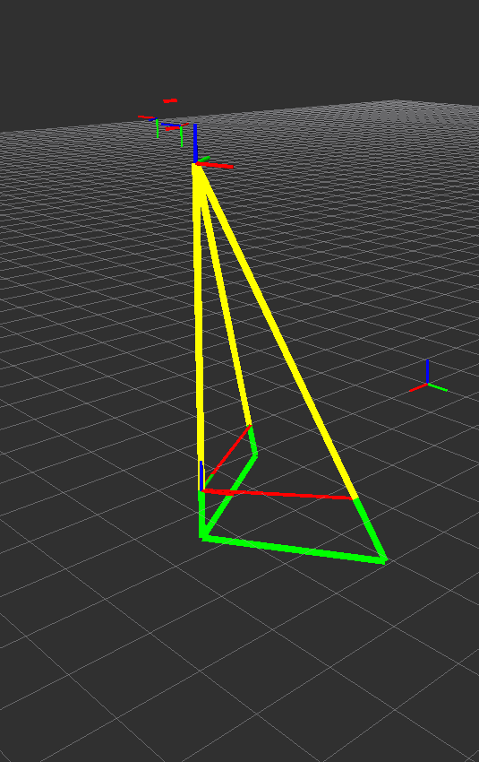
In case multiple solutions have been found, you can look at each one by selecting the respective item in the list. The pose will then be visualized in rviz.
Once the most plausible pose has been selected, click "Start PTU" to open the automatic marker search.
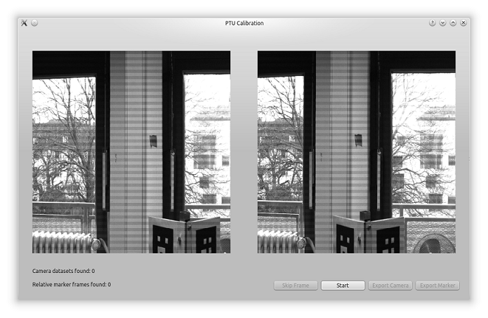
You should now get a video stream of both camera images. Make sure, both images are transmitted correctly and then press the "Start" button to start the automatic marker search.
The PTU will now automatically iterate over a predefined set of joint angles and try to recognize the calibration object's two markers during each iteration.
You can speed up the process by pressing "Skip Frame" if clearly no markers can be recognized in the current image.
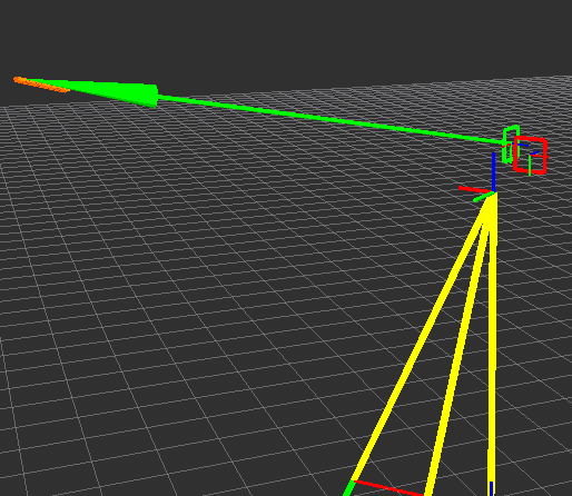
Once a marker has been recognized, the calculated transformation between the marker and the camera will be visualized in rviz (green arrow):
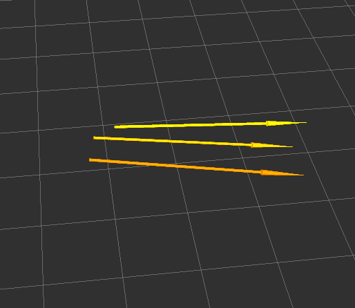
The resulting camera poses relative to the calibration object will also be visualized with small arrows point along the camera's view direction.
Once the automatic marker search has finished, press the "Export Camera" button to export the relative poses between the camera and the laser scanner to a file. You can select an already existing file of transformations to append your latest data.


