| Note: Currently this tutorial assumes you are using cob3-3. |
| |
Prepare Care-O-bot 3 for calibration
Description: This tutorial covers the preparation of Care-O-bot for calibration.Tutorial Level: ADVANCED
Next Tutorial: Automatic Camera and Robot Calibration of Care-O-bot 3
Start Care-O-bot
- Start roscore
Start Care-O-bot software (see cob_bringup).
- Make sure Base, Torso, Arm, Head-axis and Cameras are initialized and running.
- Verify that you have write access to the cob_calibration_data package, i.e. you need to create a temporary overlay for this package. All calibration results will be saved there automatically.
Attach calibration pattern to arm
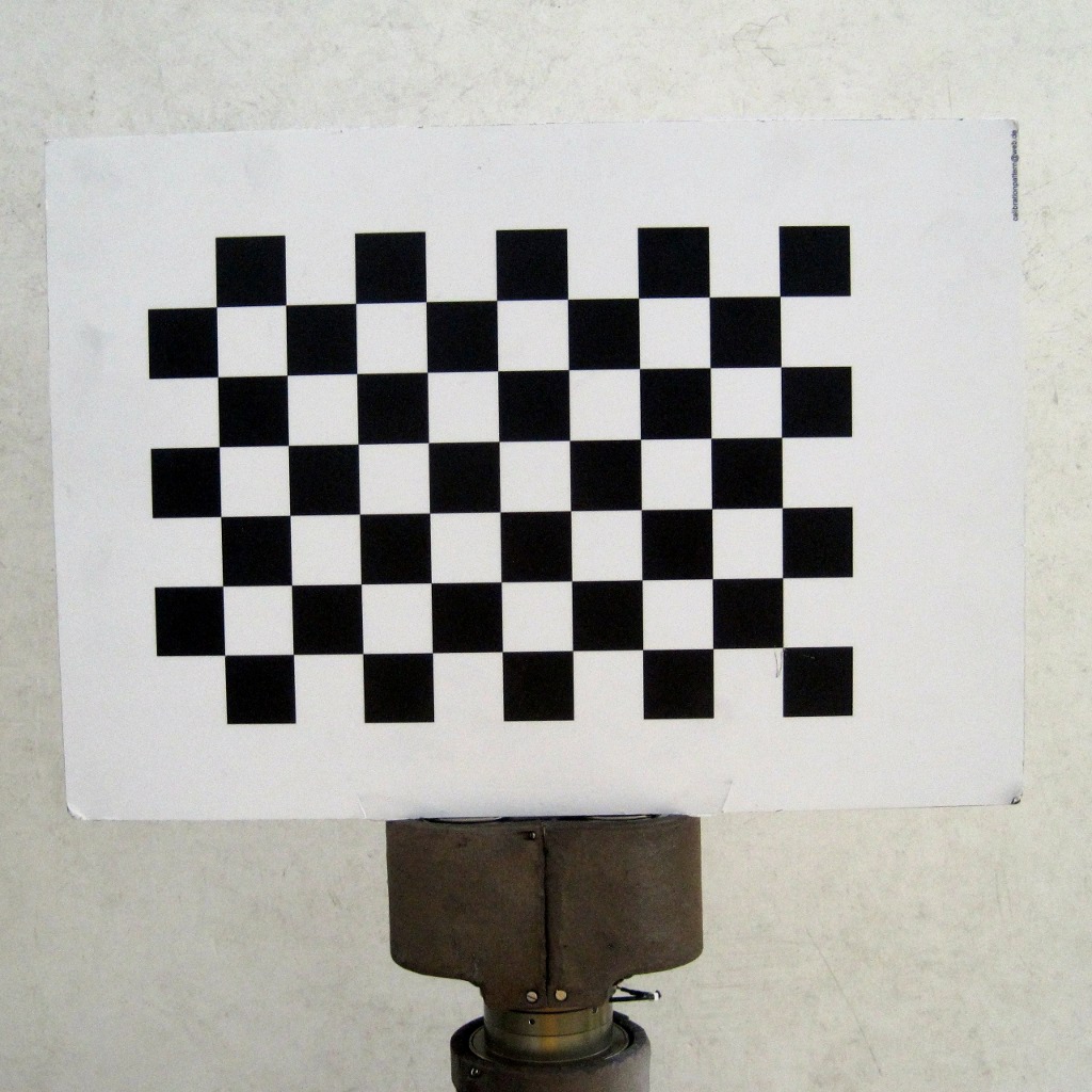
The calibration procedure uses a checkerboard calibration pattern which has to be mounted to the arm of Care-O-bot in a fixed position. The pattern has 10 horizontal and 7 vertical squares (9 by 6 inner square corners; thus the checkerboard is called cb_9x6) and the square size is 30mm.
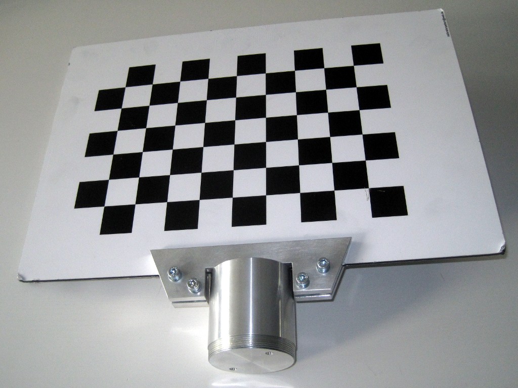
At Fraunhofer we use a calibration pattern fixture which can be mounted to the arm instead of the robotic hand:
Technical drawings from the fixture can be downloaded in a tarball calibration_fixture.tar.gz.
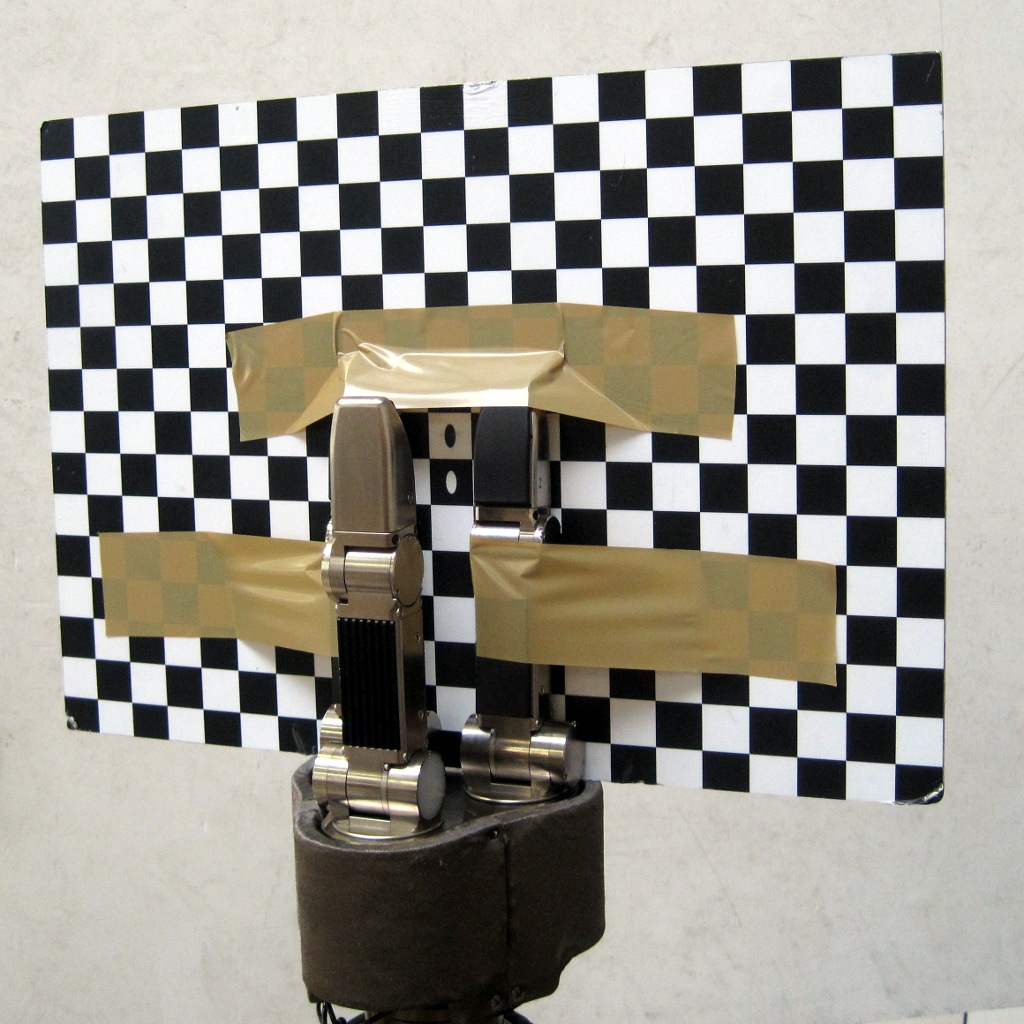
If you do not have a fixture you can also tape the calibration pattern to the hand:
To mount the calibration pattern follow these steps.
- First, move the arm to the "pregrasp" position using the dashboard. Second, move it to the calibration position:
roslaunch cob_calibration_executive move_arm_to_calibration_position.launch
- Trigger the emergency stop.
- Remove the Schunk SDH hand from the arm by unscrewing the big flange.
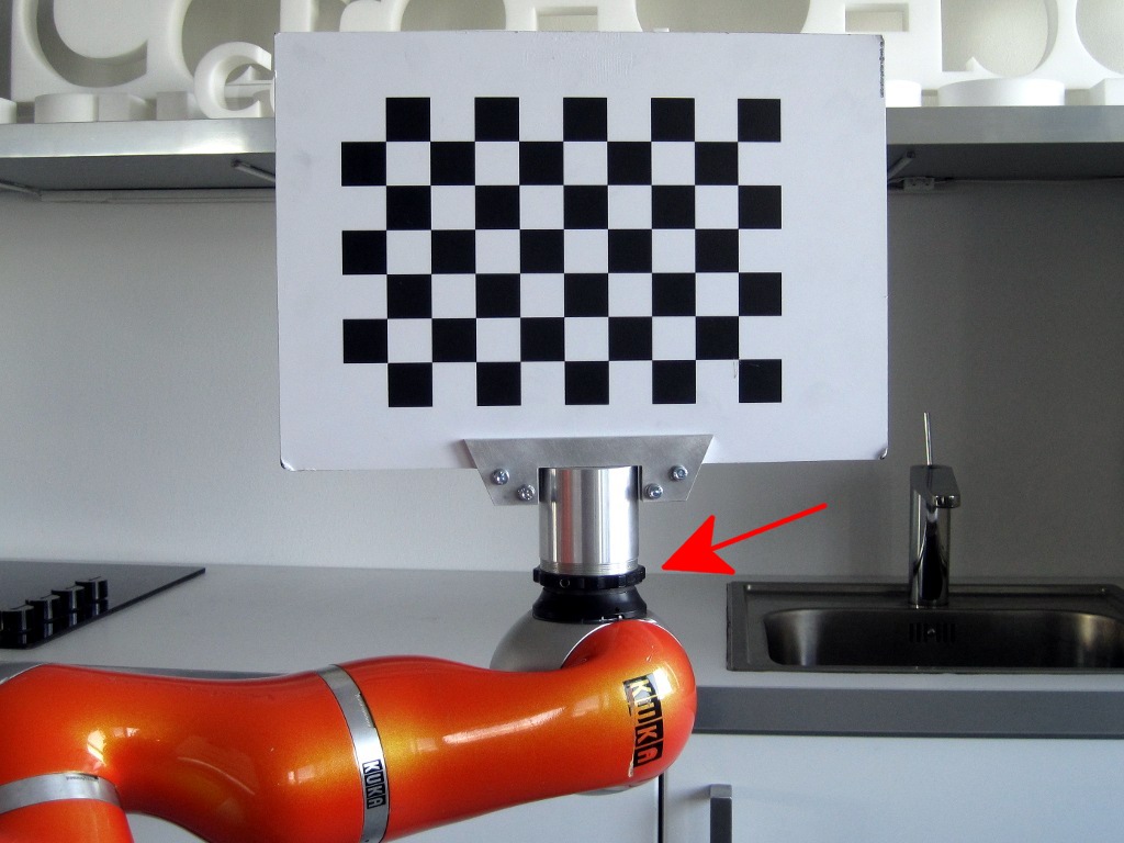
- Attach the calibration pattern to the arm. The flange is marked with the red arrow.
- Release the emergency stop and recover all components.
Check/update torso reference position
Move torso to home position using the dashboard.
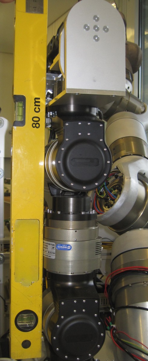
Use aluminum level to check if torso is vertical. If torso is vertical in home position skip to the next step.
Use joystick (see cob_teleop) to move torso in vertical position while checking with aluminum level.
Record current joint angles with
rostopic echo /torso_controller/state
and update the torso_*_ref positions by adding the values from torso_controller/state to the reference offsets in cob_calibration_data/ROBOT/calibration/calibration_offset.urdf.xacro.
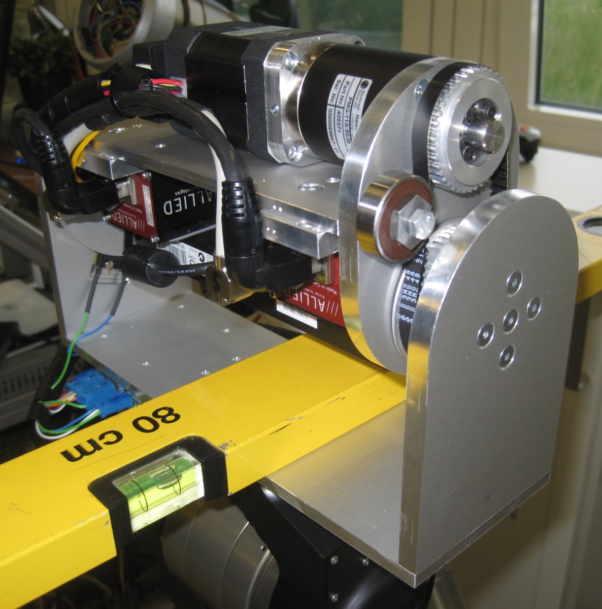
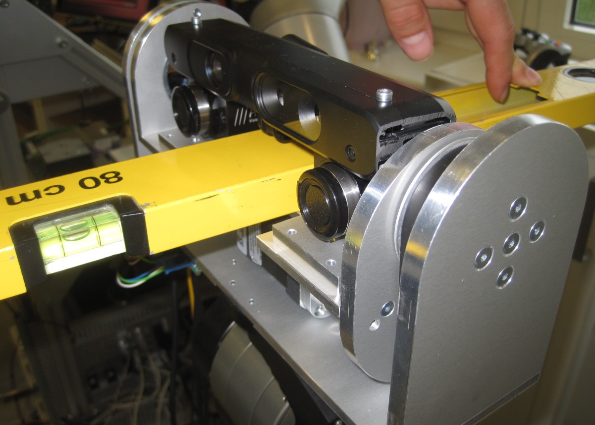
Move head axis back (i.e. "back"-position in the "eyes" column of the dashboard). Use aluminium level to verify that head axis plate is horizontal. If necessary update the head_axis_ref position in cob_calibration_data/ROBOT/calibration/calibration_offset.urdf.xacro by adding the head_controller/state value.
- Restart robot software (bringup.launch) to load updated ref positions.
Now that Care-O-bot is prepared, continue with the calibration step: electric. groovy


