Laser Camera Calibration
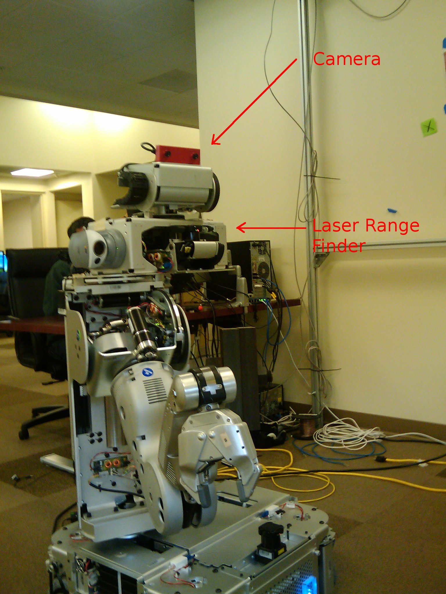
The laser_camera_calibration package simultaneously calibrates the extrinsic parameters of the cameras and laser range finders on the robot.
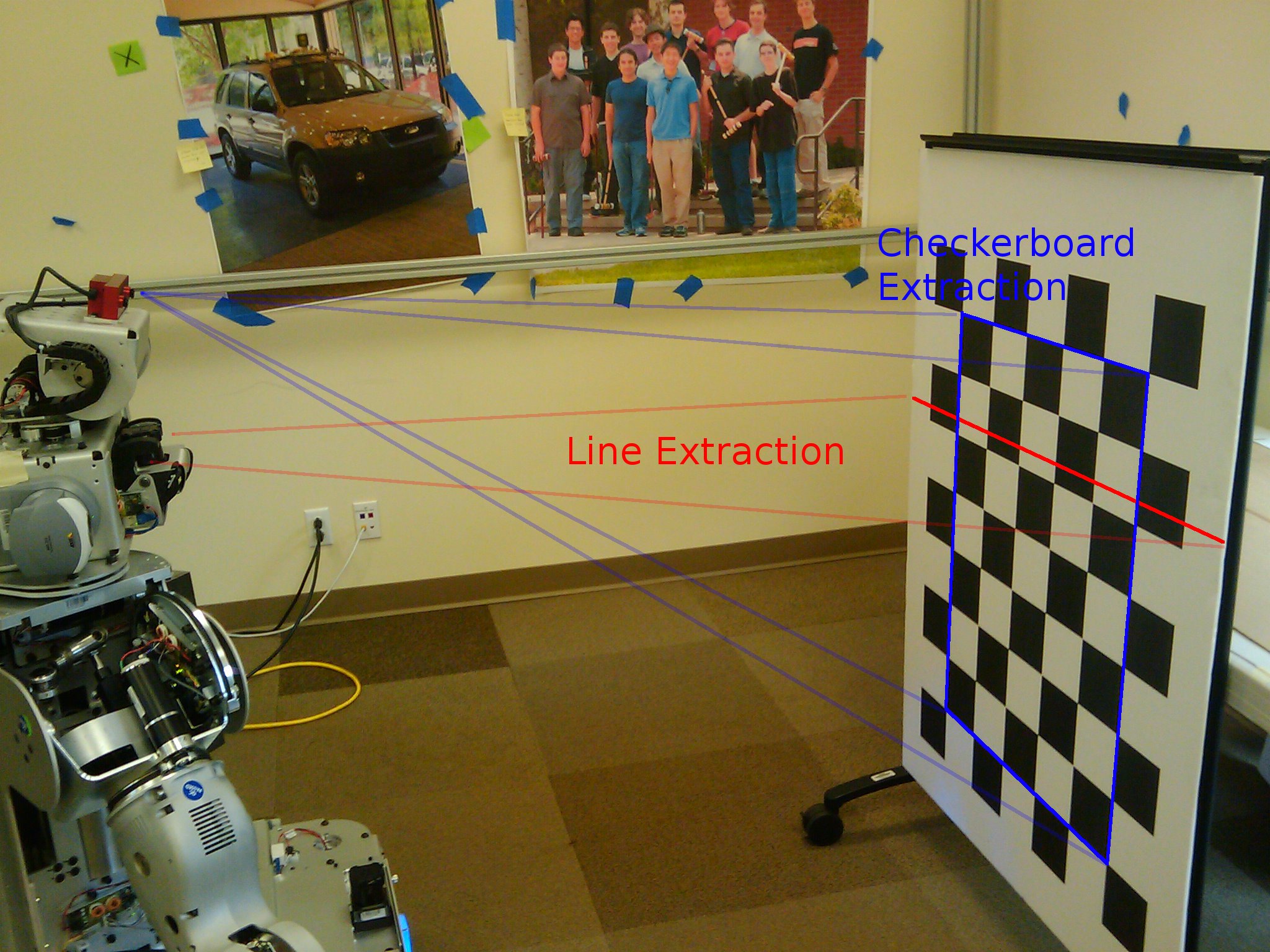
The laser range finder usually gives one 2D scan and is connected through a kinematic chain to the camera while the camera can detect the 6D pose of any checkerboard patterns. The calibration process tracks measurements about a calibration pattern in both (or any number) of sensors and tries to adjust their 6D pose offset with respect to the robot links they are mounted on while minimizing this error. The laser can extract a line segment that it knows lies on the plane of the checkerboard pattern. The camera can extract the 6D pose of the checkerboard, which it then uses to find the plane. There is a distance metric between a line segment and a plane.
Requirements
Need to have octave installed along with the optim toolbox. In recent distributions, these toolboxes can be found in the package managers. Otherwise, get them from the octave-forge project.
Gathering Data
Once the basic robot services are started like controllers and cameras, run
roslaunch `rospack find laser_camera_calibration`/gatherdata.ros.xml
To start recording data. This will create a bag file automatically whenever the camera detects a checkerboard pattern.
Press Ctrl+C to stop recording data and then start an octave process to perform the minimization by running
Calibrating
roslaunch `rospack find laser_camera_calibration`/startcalibration.ros.xml
In order to feed the data captured to the calibration process run rosplay on the bag file. For example, if the bag file is called lasercamcalib.bag then run
rosplay -a -s 1 lasercamcalib.bag
Once rosplay is done, press Enter on the command prompt for roslaunch. (If Enter isn't registering, try running runperception.m in a separate octave window from roslaunch). The entire calibration process should take 15-20 minutes.
The final Tcamera and Tlaser matrices are the relative transforms between the head_tilt_link and laser_tilt_link.
Removing Outliers
Outliers in detecting the checkerboard line from the laser scans are very frequent, and the thresholds controlling them need to be tweaked to every user's specific setting. In startgathering.m, there are a couple of parameter that control where the expected checkerboard scan should be:
- distthresh - specify max valid distance of checkerboard, currently 2m
- anglethresh - specify max out of plane rotation, default is pi*3/8
- minlinelength/maxlinelength - specify the minimum and maximum lengths of the checkerboard plane to expect from the laser scan.
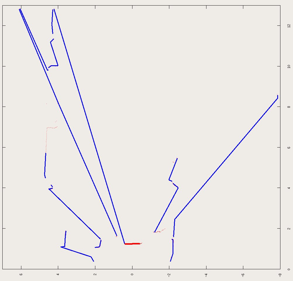
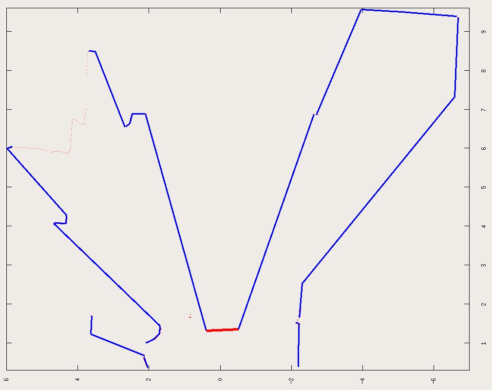
When processing the data, it is highly recommended that the accepted samples are examined (thick red line should show up whenever a samples is accepted). If anything is accepted wrongly, you might have to tweak the acceptance parameters to adjust to your settings. In the end, the startgathering.m saves all the extracted data to a calibdata.mat file, which can be opened and spurious indices removed (indices for samples are shown during the 'adding data' message). Once calibdata.mat is edited, just start the calibratevalues.m function.
Extra Features
The calibration loop can also calibrate the joint offsets along the kinematic chain from the camera to the laser. The first and last joints along this chain should be ignored since the 6D pose calibration of each sensor takes this into account. In octave/calibratevalues.m set jointnames to the joint names that should be calibrated.
Internal Details
The calibration script is written in octave and can be found in octave/runcalibration.m. It first gathers all the measurements using octave/startgathering.m. After that is done finds the best fitting extrinsic parameters using octave/calibratevalues.m. The intermediate data from octave/startgathering.m are saved in calibdata.mat, which can be used directly by octave/calibratevalues.m.
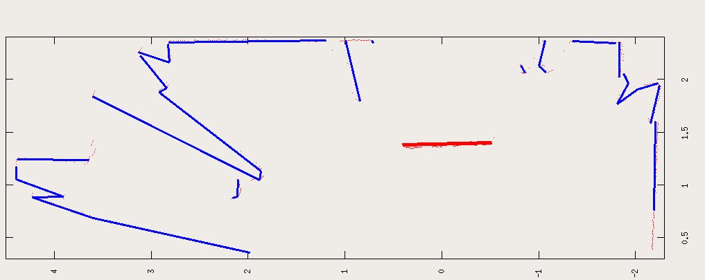
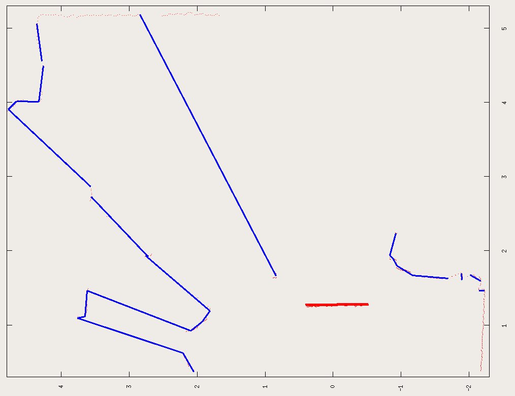
Examples of checkerboard extraction from every laser scan. The detected checkerboard is shown in red, the blue lines are a line segmentation of the laser scan using the Split-and-Merge segmentation Algorithm (octave/SegmentLines.m).
TODO
- have a small app that overlays the laser measurements on top of each camera image so we can validate our results
- use the right camera to get better depth estimates.


