| |
Connecting your GNC project to the simulator
Description: Shows how to connect a GNC project to the simulator using the template_gnc package.Tutorial Level: BEGINNER
Contents
The important feature of this framework is that your GNC project will be exactly the same in the simulation environment as when deployed on the real system. To achieve this, we need to follow a special architecture, already implemented in the template_gnc package.
Creating and testing your first GNC package
Installation
Follow the instructions of the template_gnc package to install it in your catkin workspace, and update the code with the name of your GNC project. In this tutorial we assume that your project is named test_rocket_gnc as proposed in the package instructions, but any other name would work.
Note: Don't forget to link your new package to another git repository if you want to version control your modifications.
First closed-loop simulation
Your new GNC package already contains a basic implementation of the Navigation, Control and Guidance algorithms to stabilize the rocket orientation and reach a target apogee. We can thus directly launch a simulation with this GNC:
roslaunch test_rocket_utils test_rocket_SIL.launch
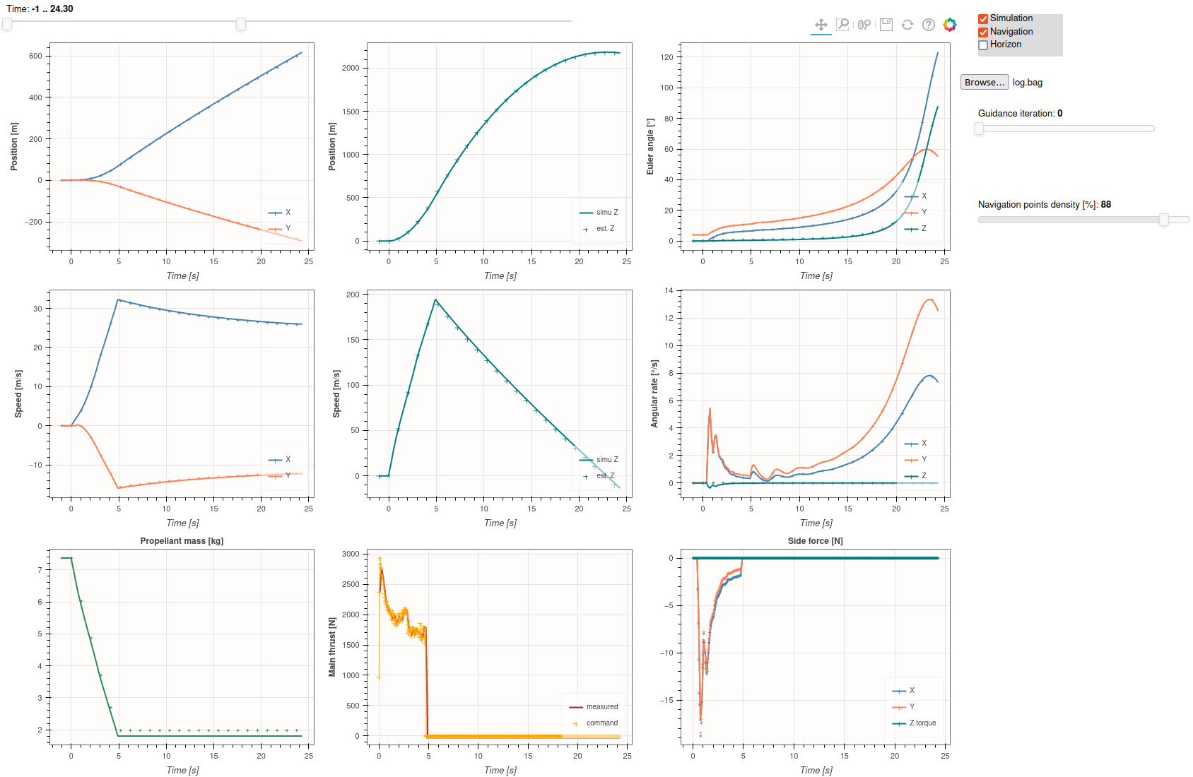
This command starts the simulator nodes and your GNC nodes, and open the same graphical interface as in the previous tutorial. You can start the simulation with the Publish button, and see the rocket reaching close to 2000 meters of apogee. Hit CTRL+c in the terminal to stop the simulation.
Try changing the target altitude height in test_rocket_utils/config/environment_parameters.yaml to test the performance of the GNC.
Analyzing the results
In simulation mode (SiL) the flight data are recorded using rosbag in the file real_time_simulator/log/log.bag. We can use the post-processing tools of the real_time_simulator package to analyze it.
roscd real_time_simulator
python3 postProcess/postProcess.py
This launches a classic Matplotlib windows displaying the simulated and estimated state of the vehicle, as well as the controlled and measured commands.
You can also use the bokeh application to display a more interactive version of these plots:
roscd real_time_simulator
bokeh serve --show postProcess/fancy_plotter.py

Upgrading the GNC
Let's see what's inside this GNC package. In the launch file test_rocket_SIL.launch, we first include all necessary nodes from the simulator:
<include file="$(find real_time_simulator)/launch/rocket_sim.launch" />
As before, we also include the configuration files, this time from the GNC package.
Finally we launch the nodes of the GNC:
  <node name="test_rocket_control" pkg="test_rocket_control" type="test_rocket_control_node" output ="screen"/>
  <node name="test_rocket_navigation" pkg="test_rocket_navigation" type="test_rocket_navigation_node" output ="screen"/>
  <node name="test_rocket_guidance" pkg="test_rocket_guidance" type="test_rocket_guidance_node" output ="screen"/>
  <node name="test_rocket_fsm" pkg="test_rocket_fsm" type="test_rocket_fsm_node" output ="screen"/>
  <node name="av_interface" pkg="rocket_utils" type="av_interface.py" output ="screen"/>
We launch one node for each of the three algorithms (Guidance, Navigation, and Control), as well as test_rocket_fsm that runs the state machine to define if we are in Idle, Rail, Launch or Coast mode. The av_interface nodes is the interface between your GNC and the input/output of your vehicle. Here it just redirects the simulation data to the GNC.
Guidance
This algorithm computes a trajectory from the current state to the apogee, to be tracked by the Control algorithm. The trajectory is sent as a custom Trajectory message, which is simply an array of Waypoint messages, defined as:
float32 time
geometry_msgs/Point position
geometry_msgs/Vector3 speed
float32 propeller_mass
float32 thrust
In our template example, we only computes a linear trajectory in 3D position, and leave the other fields empty. You can improve this algorithm by computing a more realistic trajectory, and filling the other fields of the message to better assist the Control algorithm.
Additionally, this algorithm predicts the apogee of the rocket to send the shutdown command to the engine at the right time. ( !! Not implemented in new-template-gnc !! -> to do for nicer tuto
Try to compute the trajectory as a piece-wise parabolic function in position, and piece-wise linear function in velocity. You can also compute the evolution of thrust and mass from this simplified model.
Navigation
This algorithm estimates the state of the vehicle using direct integration of the IMU data. A simple one-dimensional kalman filter then corrects the altitude estimation by comparing it with the barometer measurement.
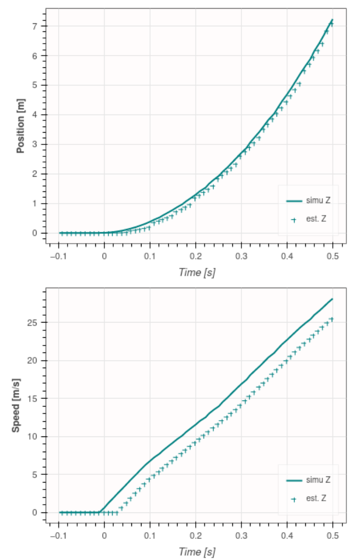
If you've run a few simulations, you probably have noticed that the resulting apogee is significantly higher than the target one. The issue is not from the Guidance algorithm, but actually from Navigation, as this simple algorithm cannot properly estimates the vertical velocity, which is a very important information to predict the apogee.

This error in velocity estimation comes from the delay of the sensors, as we only start integrating the acceleration into a velocity after detecting the liftoff, which means the rocket will already have a significant speed when we start the Navigation algorithm. We clearly see this in the plot above, the error in velocity is actually a pure delay. The error in position on the other end is quickly corrected by the kalman filter.
One solution to this is to integrate a velocity correction into the kalman filter, as it was done in bellalui_gnc. Another simpler way is to increase the sensor sampling frequency (defined in real_time_simulator/config/perturbations_parameter.yaml) as it is the main source of delay.
Try to implement a better velocity estimation, or an algorithm to compensate delay.
Control
This algorithm should track the reference trajectory defined by guidance, during the time the engine is ignited. This template implementation is only a linear controller proportional to the angular rate, but you can add more terms to track the position and orientation too.
The output of this algorithm is a message of type GimbalControl, which send commands to the simulated gimbal actuator:
Header header
float64 outer_angle
float64 inner_angle
float64 thrust
Try to implement a two-stage PID controller to stabilize both the position and orientation to zero.


