| |
RGBD depth correction: version 1 (work in progress)
Description: This tutorial shows how to use the depth calibration procedure to correct a point cloud from an ASUS PrimeSense sensor.Tutorial Level: INTERMEDIATE
Requirements
ASUS PrimeSense camera
- Linear guide rail
- Large, flat wall
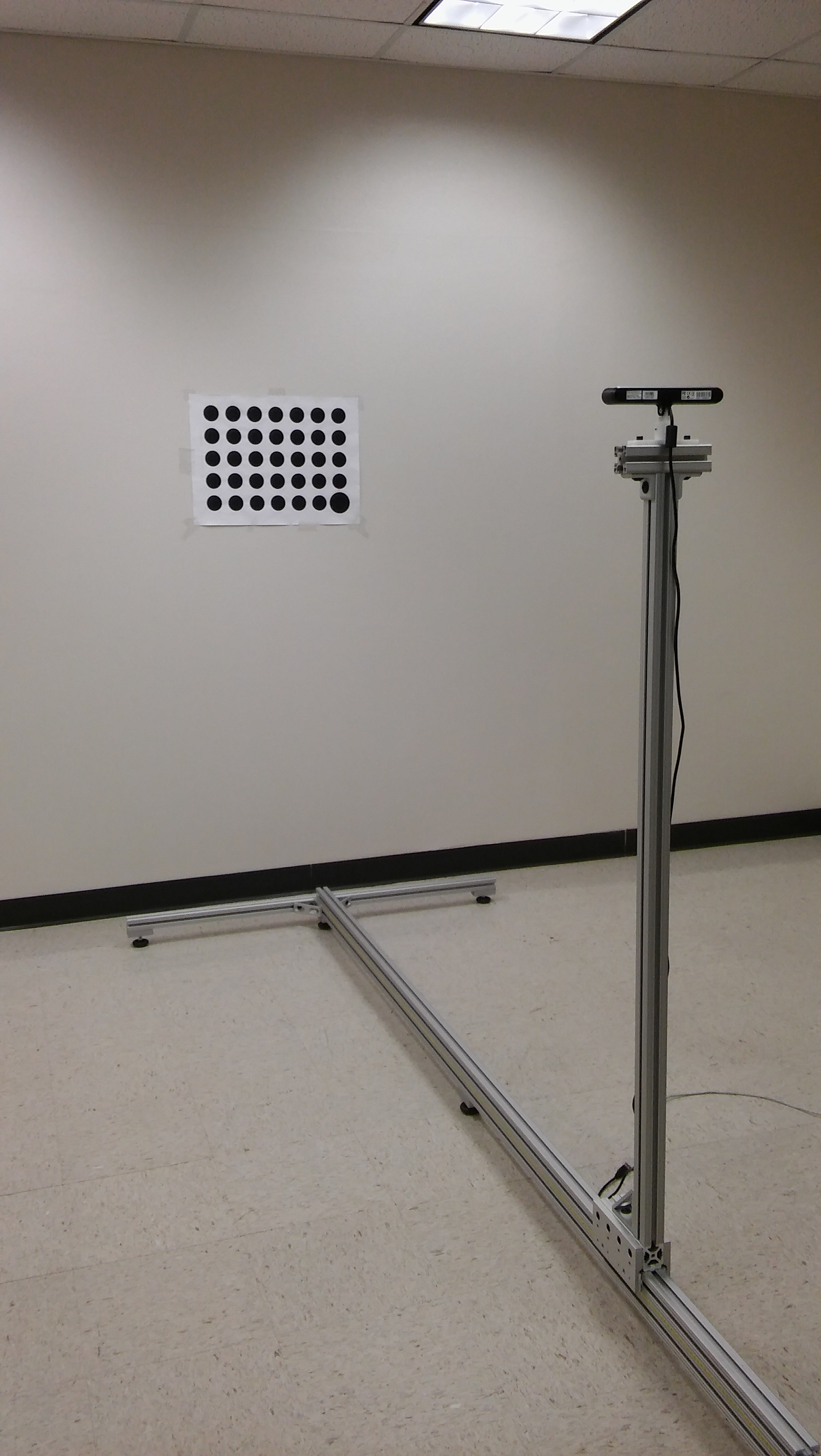
- Calibration target
- When choosing a calibration target, keep in mind that the target must be able to be seen by the camera at all distances over which you are calibrating. Check the closest and furthest point to ensure that the target is visible and found by the industrial_extrinsic_cal target_finder node.
Setup
This assumes that the surface the target is on is flat and featureless. If the surface is not flat, then any artifacts will be saved in the depth correction map, and cause incorrect results when the sensor is moved to a different location.

Choose a working range over which you will calibrate and operate the camera. Make sure to take images over the whole working range. If the camera is operated outside of the range that it is calibrated in, then the extrapolated depth correction may not perform well.
- Set the camera on the rail at the close location, verify that the target can be found
- call the target finder service and provide reasonable values for the position and orientation of the target (within 0.5m and +/- 30 degrees is sufficient)
rosservice call /TargetLocateService "allowable_cost_per_observation: 1.0
roi: {x_offset: 0, y_offset: 0, height: 480, width: 640, do_rectify: false}
initial_pose:
  position: {x: 0.0, y: 0.0, z: 1.0}
  orientation: {x: 0.707, y: 0.0, z: 0.0, w: 0.707}"
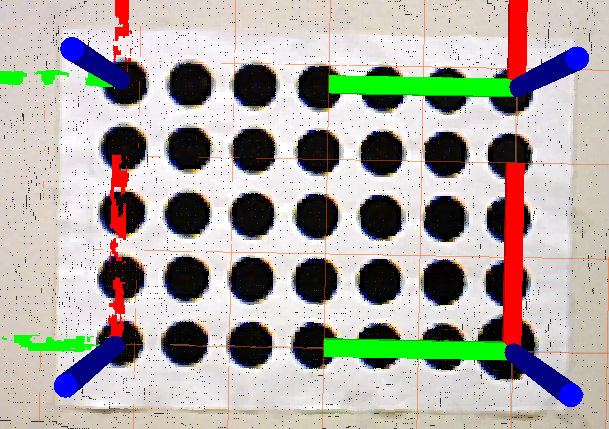
- verify that the target is found
- call the target finder service and provide reasonable values for the position and orientation of the target (within 0.5m and +/- 30 degrees is sufficient)
- Move camera to the back location, verify that the target can be found
Procedure
- Modify the launch file 'calibrate.launch' to include the parameters for the target that you are using
- rows/columns
- diameter/spacing
roslaunch rgbd_depth_correction calibrate.launch
- Set the camera at the back most location
rosservice call /pixel_depth_correction
- Move the camera to a series of positions and collect the image
- move camera to new position (~10 positions in total, evenly distributed across the full calibration range)
rosservice call /store_cloud
After all images have been collected rosservice call /depth_calibration
- This step may take some time to solve for the depth correction terms.
Validation
- Modify the correction.launch file to match the target size you are using
- rows, columns, size, spacing for the extrinsic calibration node
- TF frame locations. The (x,y) location should correspond to the corners of your target where the origin is located in the center of the largest circle
- Set camera_info_urls to the pathway that your calibration files are saved if a different location was provided in the calibration step.
roslaunch rgbd_depth_correction correction.launch
rosservice call /calibration_service "allowable_cost_per_observation: 1.0"
- Visualize the corrected point cloud and verify that the target TF frames align with the centers of the circles you provided. Insert a grid located at the target origin and use it to compare the flatness of the point cloud. For comparison, switch between the corrected cloud and the uncorrected. Move the camera to several positions and run the calibration service each time. Check to make sure that the point cloud looks correct at each location.


