Overview
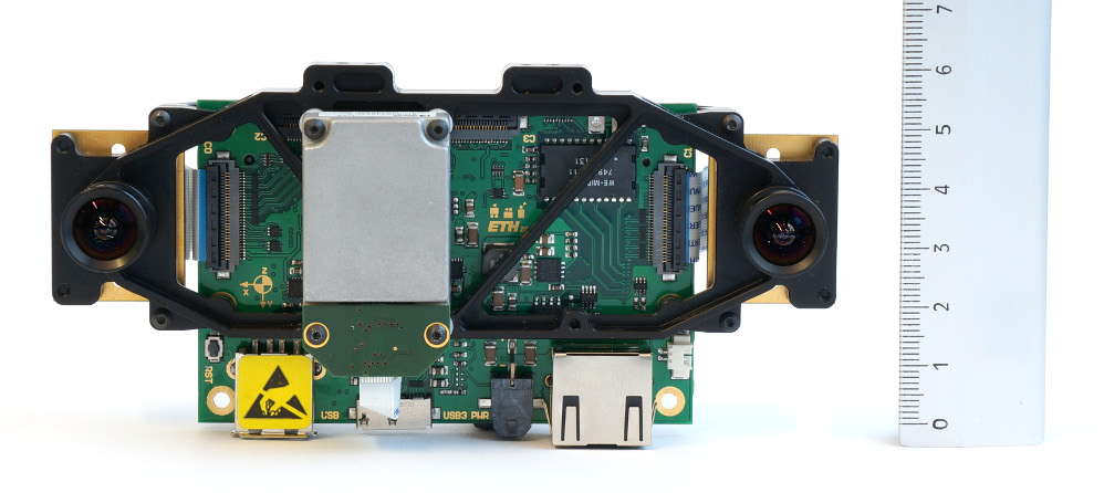
This stack describes the ROS interface to the Visual-Inertial (VI-) Sensor developed by the Autonomous Systems Lab (ASL), ETH Zurich and Skybotix. This sensor provides fully time-synchronized and factory calibrated IMU- and stereo-camera data streams. A detailed spec sheet of the sensor can be found here.

Contributors and References
The sensor hard- and software was developed by:
Janosch Nikolic <janosch.nikolic AT mavt.ethz DOT ch>
Joern Rehder <joern.rehder AT mavt.ethz DOT ch>
Michael Burri <michael.burri AT mavt.ethz DOT ch>
Pascal Gohl <pascal.gohl AT mavt.ethz DOT ch>
Thomas Schneider <thomas.schneider AT mavt.ethz DOT ch>
Pascal Strupler <pascal.strupler AT skybotix DOT com>
Fabio Diem <fabio.diem AT skybotix DOT com>
Sammy Omari <sammy.omari AT skybotix DOT com>
For technical support questions, please use support@skybotix.com .
If you use the sensor for your academic work please cite the following paper:
Nikolic, J., Rehder, J., Burri, M., Gohl, P., Leutenegger, S., Furgale, P. T., & Siegwart, R., A Synchronized Visual-Inertial Sensor System with FPGA Pre-Processing for Accurate Real-Time SLAM. IEEE International Conference on Robotics and Automation (ICRA), Hongkong, China.
Powering the Sensor
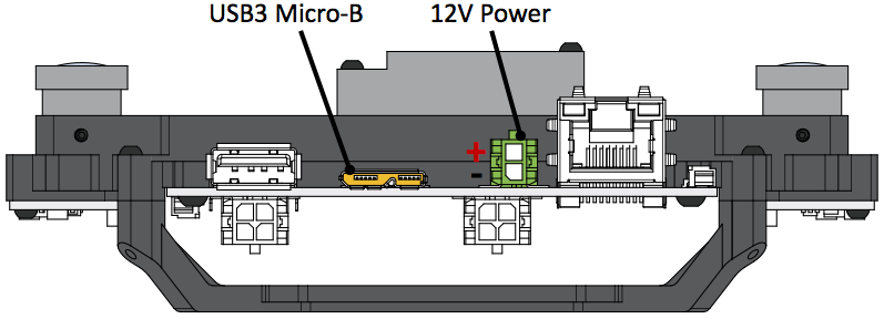
You can use the provided USB 3.0 micro-b cable to power your sensor. Your USB controller on your computer should be able to provide at least 500 mA. If your USB port provides less than 500 mA, the sensor might still start up, but the image stream will be flickering in this case.
Otherwise, you can connect your sensor to a 12 V power supply using the Molex Micro-Fit 3.0 connector and contacts supplied with the sensor. Please refer to the figure below for polarity information. The input voltage can vary from 10-15V, so connecting the sensor directly to a battery is feasible.

Connecting the Sensor
Using the Ethernet cable that came with your sensor, you can connect your VI-sensor to a computer or to a network switch. Please note, that the network and the computer should support Gigabit Ethernet as a 100 MBit LAN does not provide sufficient bandwidth for the sensor data. If you dont have a Gigabit ethernet port but a USB 3.0 port (for example in the Odroid-XU board), a USB3.0 to GigE adapter should work fine. We successfully tested the ASIX AX88179 chipset which is widely available. Any other standard-compliant USB3.0 dongle should do the job. As the Ethernet port on the sensor does not follow Ethernet standards, use only the provided cable to connect your sensor to either your PC or a network hub/switch.
When the sensor is powered-up (boot up can take up to 20-30s) and connected directly to your computer, the sensor will act as a dhcp server and you will obtain an IP (most likely 10.0.0.5). In case the sensor is connected to a network with an existing dhcp server, the sensor should automatically disable its dhcp server and obtain an IP from the network.
If you want to run the sensor driver in a virtual machine (this is possible), please refer to the FAQ .
Interfacing the Sensor From ROS
You can either create a standalone executable for accessing the vi-sensor or you can stream the vi-sensor output to ROS (Robotic Operating System) using the corresponding ROS-frontend. For the standalone interface, refer to this section.
You can download the ROS frontend and the low-level driver from our github repo into your catkin workspace (for information on how to set up your catkin workspace, please refer to this tutorial).:
 #making sure you have all the necessary dependencies
sudo apt-get install libeigen3-dev libboost-dev libopencv-dev
 #change directory into catkin folder
 cd ~/<CATKIN_WS>/src
 #checkout low-level driver
 git clone https://github.com/ethz-asl/libvisensor.git
 #checkout ROS frontend
 git clone https://github.com/ethz-asl/visensor_node.git
 # make visensor
 cd ..
 catkin_make
 # add the next line to the .bashrc
 source ~/<CATKIN_WS>/devel/setup.bash
Start a roscore in a separate terminal:
roscore
Assuming that the sensor is powered and connected, you can run the driver as
rosrun visensor_node visensor_node
If there is an error (most likely failed autodiscovery), please refer to the FAQ.
If the ROS frontend started properly, you can check the image stream using
rosrun image_view image_view image:=/cam0/image_raw
rosrun image_view image_view image:=/cam1/image_raw
The IMU stream is at the topic /imu0
rostopic echo /imu0
If you have downloaded and properly installed the vi-sensor calibration files (see this section), you can launch the ROS block-matcher stereo pipeline using
roslaunch visensor_node dense.launch
If the disparity output is very noisy, please refer to the FAQ.
The VI-sensor comes preconfigured with standard settings, such as automatic gain and exposure control for example. If you want to change these parameters, you can do this using rqt_configure. This tool allows the fine-grained control of the imaging sensors (e.g. gain-, exposure settings etc.) and the IMU.
Running the VI Sensor Standalone (Without ROS)
You can create your own applications without ROS by linking it to the low-level sensor driver library. Check out the sensor library
git clone https://github.com/ethz-asl/libvisensor.git
Make sure that you installed all necessary Ubuntu packages
sudo apt-get install libeigen3-dev libboost-dev
Build the package and install it system-wide.
cd libvisensor
./install_libvisensor
In case you don't want to install the library system-wide, you can also simply build it using
cd libvisensor
mkdir build
cd build
cmake ..
make
In this case, you have to ensure that your applications can find the library files and headers.
To see sample (stand-alone) projects, please refer to our standalone application github repo.
For now, this repo contains two sample standalone applications for the VI-Sensor:
- vi_sensor_interface: A very basic interface to the VI-Sensor. Receives images and IMU messages and displays it using openCV.
vi_sensor_stereo_block_matcher: Applies rectification to Vi-Sensor images and subsequently computes the disparity image using standard openCV block matcher. Intrinsic & extrinsic calibration parameters for rectification are downloaded from VI-Sensor.
 # checkout sample applications
 git clone https://github.com/skybotix/visensor_sample_applications
 # build one
 cd vi_sensor_interface
 mkdir build
 cd build
 cmake ..
 make
If the sensor is connected, you can start the application
../bin/visensor_interface
and you should now see both image streams displayed. The block matcher stand-alone application is also a CMake project and can be compiled accordingly.
Sensor Calibration Data
The VI-Sensor is calibrated for camera intrinics as well as IMU-camera or camera-camera extrinsic respectively. The calibration follows the standard openCV camera calibration (pinhole camera model + radial tangential lense model).
The factory calibration is stored in the VI-Sensor firmware and is sent to the sensor library when starting the driver. In the ROS interface, the full calibration is published with every image in the message /camX/calibration . You can also obtain the calibration using the ROS service call TODO, e.g. when you start up your own Visual-Inertial Odometry algorithm. This message/service call contains the extrinsics of the cameras w.r.t. IMU as well as the camera intrinsics.
To support the standard vision pipelines of ROS, the corresponding calibration information is published under /camX/camera_info . Please note that this calibration does not contain any information concerning the extrinsics of the camera w.r.t IMU. For this, use the /camX/calibration message as it is more complete.
If you want to update the sensor calibration, e.g. when you changed the camera-imu configuration, please refer to this section.
If you want to obtain the calibration parameters in a stand-alone application (without ROS), please refer to this section where an code example is discussed. .
Running the Visual-Odometry Framework FOVIS
You can download the fovis framework in your ROS catkin folder by
cd ~/<CATKIN_WS>/src
git clone https://github.com/skybotix/fovis.git
git clone https://github.com/skybotix/libfovis.git
cd ..
catkin_make
This should hopefully build the fovis framework. Start the sensor driver with
rosrun visensor_node visensor_node
You can now run the framework with
roslaunch fovis_ros fovis_stereo.launch
Voila, you should now have a working VO framework running. You can check the feature correspondences with
rosrun image_view image_view image:=/stereo_odometer/features
Please note that displaying and rendering this videostream consumes considerable CPU load. If you want to run fovis with a considerably reduced CPU load (at the cost of sacrificing a bit of accuracy), you can remove the # from
#add_definitions( -DUSE_FAST_SETTINGS )
in the CMakeLists.txt in the libfovis directory. On an Intel i7, this will reduce the CPU load for a single core from approximately 35% to less than 20%. For more info on how to tune the gains, please refer to the fovis paper.
Please note that the FOVIS framework only runs on x86 platforms as this implementation requires SSE2 functionality.
Running the Visual-Odometry Framework VISO2
Equivalently to fovis, you can download the viso2 framework in your ROS catkin folder by
cd ~/<CATKIN_WS>/src
git clone https://github.com/skybotix/viso2.git
cd ..
catkin_make
This should hopefully build the viso2 framework. Start the sensor driver with
rosrun visensor_node visensor_node
You can now run the framework with
roslaunch viso2_ros demo.launch
Voila, you should now have a working VO framework running. In order to tune the framework for speed or accuracy, check out the viso2 ROS wiki page.
Please note that the VISO2 framework only runs on x86 platforms as this implementation requires SSE2 functionality.
Updating the Sensor Firmware
If you receive a Newsletter from us that a new firmware version is available, you can update the sensor using the script from our visensor_tool repo. The Readme in this repo provides detailed instructions on how to update the sensor.
Calibrating the Sensor
The sensor itself is factory-calibrated in terms of ex- and intrinsic camera and imu calibrations. However, if you reconfigure/rearrange the camera-imu configuration, you can recalibrate the sensor using the Kalibr framework. This is specifically tailored to the VI-Sensor and comes preconfigured with all necessary configuration files for the VI-Sensor IMU and cameras as well as a tutorial for the VI-Sensor. Once the Sensor is calibrated successfully, you can upload the camchain calibration file to the VI-Sensor using the calibration upload script from our visensor_tool repo.
Please note that the upload will overwrite the factory calibration. If you need to backup your factory calibration, please contact please contact our support support@skybotix.com .
Accessing The Sensor Inside a Virtual Machine
You should be able to access the sensor inside a virtual machine. As a default configuration, VMs usually use a NAT network configuration, which blocks the sensor datastream. Instead, we have to set the network configuration of the Gigabit Ethernet adapter to "bridged". Using this setting, the VM will have direct access to the adapter and subsequently to the sensor. If you connect your sensor directly to your PC, the network card inside your VM should have the IP 10.0.0.5 if everything is configured correctly. We have tested this functionality under VirtualBox 4.3 and VMWare Workstation 10.
FAQ
For more information please visit the FAQ page at http://www.skybotix.com/faq/


