Show EOL distros:
Package Summary
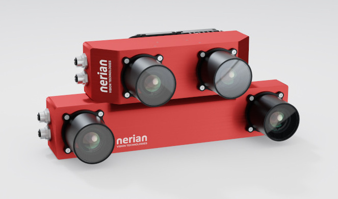
Driver node for Scarlet and SceneScan stereo vision sensors by Nerian Vision GmbH
- Maintainer status: developed
- Maintainer: Konstantin Schauwecker <konstantin.schauwecker AT nerian DOT com>
- Author: Nerian Vision Technologies <service AT nerian DOT com>
- License: MIT
- Source: git https://github.com/nerian-vision/nerian_stereo.git (branch: master)
Package Summary
Driver node for SceneScan and SP1 stereo vision sensors by Nerian Vision GmbH
- Maintainer status: developed
- Maintainer: Konstantin Schauwecker <konstantin.schauwecker AT nerian DOT com>
- Author: Nerian Vision Technologies <service AT nerian DOT com>
- License: MIT
- Source: git https://github.com/nerian-vision/nerian_stereo.git (branch: master)
Package Summary
Driver node for Scarlet and SceneScan stereo vision sensors by Nerian Vision GmbH
- Maintainer status: developed
- Maintainer: Konstantin Schauwecker <konstantin.schauwecker AT nerian DOT com>
- Author: Nerian Vision Technologies <service AT nerian DOT com>
- License: MIT
- Source: git https://github.com/nerian-vision/nerian_stereo.git (branch: master)
Package Summary
Driver node for Scarlet and SceneScan stereo vision sensors by Nerian Vision GmbH
- Maintainer status: developed
- Maintainer: Konstantin Schauwecker <konstantin.schauwecker AT nerian DOT com>
- Author: Nerian Vision Technologies <service AT nerian DOT com>
- License: MIT
- Source: git https://github.com/nerian-vision/nerian_stereo.git (branch: master)
ROS2 repository: https://github.com/nerian-vision/nerian_stereo_ros2
Contents
Introduction

Nerian's Scarlet and SceneScan product lines are stereo vision based 3D imaging systems for real-time 3d sensing. While Scarlet is a fully integrated unit with image sensors and image processing in one device, SceneScan connects to two industrial USB cameras that provide input image data. Both devices correlate the images of both cameras / sensors and produce a disparity map, which is transmitted through gigabit Ethernet. The disparity map describes a mapping of image points from the left camera image to corresponding image points in the right camera image. With this information it is possible to reconstruct the 3D location of every observed scene points.
Please note: since version 3.0.0 this node is no longer compatible to SP1 – the predecessor of SceneScan. Please use an older version with SP1 or the now discontinued nerian_sp1 node
Installation on ROS1 and ROS2
On Ubuntu Linux, please use the following commands to install the official package for your current ROS version.
sudo apt-get update
sudo apt-get install ros-`rosversion -d`-nerian-stereo
These commands work for both, ROS1 and ROS2 distributions.
Should there not be an appropriate package for your system and ROS version, please checkout the git repository and compile the code using catkin/colcon.
ROS Node
The data delivered by Scarlet / SceneScan can be received using the available open source API. Using the API directly is recommended for high performance applications with ROS1. Alternatively the nerian_stereo ROS node can be used for publishing the received data as ROS messages. A Nodelet version is also provided for ROS1.

Published Topics
The node can publish the received data through three different topics:
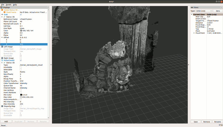
/nerian_stereo/point_cloud (sensor_msgs/PointCloud2)
- A point cloud, which is obtained by reconstructing the 3D location of each pixel in the disparity map. Optionally, the point cloud can include an intensity channel, which contains intensity data from the left rectified camera image.
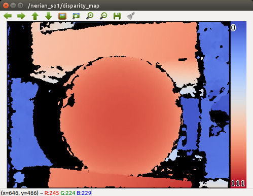
- The stereo disparity map that is computed by SceneScan. The disparity map is transmitted as an image message with mono16 encoding. Please note that the disparity map has a 4-bit subpixel resolution. This means that its values have to be divided by 16 in order to receive the true pixel disparity. Optionally, the disparity map can be color coded for visualization. In this case the encoding will be bgr8.
- The rectified image of the left camera with mono8 or mono12 encoding, if SceneScan is configured in stereo matching or rectify mode. If the device is configured in pass-through mode the unrectified left camera image will be published through this topic.
- If the SceneScan is configured in pass-through or rectify mode, then the (un)rectified right camera image will be published through this topic in mono8 encoding
- Camera calibration information for both cameras.
Launching and parameters
Example launch files are included for the ROS1 node and nodelet and for ROS2. You can run several nodes in parallel if you use more than one device, specifying the respective device address and a desired ROS node name in case of ROS1:
# For ROS1:
roslaunch nerian_stereo nerian_stereo.launch device_address:=192.168.10.10 node_name:=nerian_stereo_01

# For ROS2:
ros2 launch nerian_stereo nerian_stereo.launch.py
The behaviour of the node can be configured through various parameters. An example parameterization can be found in the included launch file nerian_stereo.launch. The following parameters are supported:
~point_cloud_intensity_channel (string, default: "mono8")
- Specifies if and how the intensity channel is encoded in the published point cloud. Available options are: none, mono8, rgb8, rgb32f.
- If enabled, the typical ROS coordinate system is used, with the x-axis pointing forward, the y-axis pointing left and the z-axis pointing upwards. If disabled, SceneScan's default coordinate system is used, with the x-axis pointing right, the y-axis pointing downwards, and the z-axis pointing forward.
- If enabled, the ROS system time will be used for timestamping the generated messages. If disabled, the timestamp transmitted by SceneScan will be used for all messages that carry sensor data. When using timestamps from SceneScan, it should be ensured that SceneScan is synchronizing its clock to an external reference .
- Selects the color scale for color coding of the disparity map. Possible values are "none", "rainbow" and "red_blue".
- If enabled, a legend will be added to the color coded disparity map.
- ID of the frame that will be set for all transmitted messages.
- Host name or IP address of SceneScan, which is used for network communication.
- Remote port number or service name that is used for network communicating with SceneScan.
- If enabled, TCP is used rather than UDP as underlying network protocol.
- Location of a YAML-file containing camera calibration data. This file can be obtained from the SceneScan webinterface. An example calibration file is provided in the repository. If this parameter is omitted, the published camera calibration information only contains the q-Matrix.
- Allows the configuration of an initial delay in seconds when launching the node. This option can be used to delay the node launch while the calibration information is downloaded.
- If set to a positive value, all points in the point cloud with a higher depth will be set to invalid.
Testing
The topics published by the nerian_stereo node can be viewed with rviz. The disparity map can also be visualized with the image_view node in ROS1 or showimage from ROS2. To do so, use can use one of the following commands:
# For ROS1:
rosrun image_view image_view image:=/nerian_stereo/disparity_map

# For ROS2:
ros2 run image_tools showimage image:=/nerian_stereo/disparity_map
In this case color coding should be activated such that the disparity map can be displayed on a screen.

For displaying the left camera image, please run the image_view node with the following command line:
#For ROS1:
rosrun image_view image_view image:=/nerian_stereo/left_image

#For ROS2:
ros2 run image_tools showimage image:=/nerian_stereo/left_image
Dynamic reconfiguration in ROS1
At launch time, the ROS1 node (and nodelet) publishes the current configuration reported by the respective device to the ROS parameter server, and can be reconfigured at run time using ROS dynamic_reconfigure, for example using the GUI:
rosrun rqt_reconfigure rqt_reconfigure
Further Information


