Only released in EOL distros:
Package Summary
Executive for capture data for running PR2's full system calibration. This package is still experimental. Expect APIs to change.
- Author: Vijay Pradeep
- License: BSD
- Repository: wg-ros-pkg
- Source: hg https://kforge.ros.org/calibration/pr2_calibration
Package Summary
Executive for capture data for running PR2's full system calibration. This package is still experimental. Expect APIs to change.
- Author: Vijay Pradeep
- License: BSD
- Source: hg https://kforge.ros.org/calibration/pr2_calibration (branch: electric_trunk)
Contents
Introduction
The PR2 calibration executive's sole goal is to aid in collecting bagfiles that hold calibration samples (calibration_msgs/RobotMeasurement), which can then be used in pr2_calibration_estimation.
This page is definitely not a full explanation of how to use this package, but rather a tool to help get started in exploring this package. If you're interested in understanding how calibration data is gathered for the pr2, you can trace through capture_data.launch
Stability
This package is still unstable, and does not have a released API.
Concepts

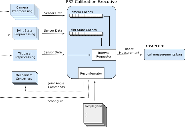
During the data capture phase of calibration, the executive brings all of the sensor processing pipelines and configuration files together to capture a series of samples. The executive follows a fairly straightforward flow when capturing each sample
- Read in the configuration of a requested sample
- Reconfigure all of the sensor preprocessing pipelines for this sample
- Command the robot to move to the specified joint positions for this sample
- Wait for the camera data and joint state data to stabilize
- Grab sensor data from the stable interval via the internal caches
Bundle the data together as a calibration_msgs/RobotMeasurement and then publish.
Running the Executive
./pr2_exec.py [samples_dir] [hardware_config_dir]
[samples_dir] - Directory that holds all the samples that need to be collected
Each file contains the configuration for each sensor, along with commands to send to controllers. We consider each file to be a sample. For the PR2, we have many samples for the left and right arm, whereas we have only one sample in the 'far' directory. This is because for far data, we don't have to keep commanding the arms, so we keep the system in this far sample's configuration until the user says they've collected enough data. You will definitely have to modify pr2_exec.py to suit your data collection needs. For the PR2, this directory, is pr2_calibration_launch/capture_data/samples_pr2_beta
[hardware_config_dir] - Directory that holds definitions for the sensors and hardware that we want to command, as described in Defining Sensors/Hardware
Defining Sensors/Hardware
Using Actions For Reconfiguration
There are many preprocessing nodes that need to be reconfigured for each sample. One way of doing this is with dynamic_reconfigure. However, the preprocessing nodes in robot_calibration all use actions. The processing nodes each expose an action interface, where the goals are actually the requested configuration. This goal can never SUCCEED, it remains ACTIVE until it is PREEMPTED by a new goal.
Cameras
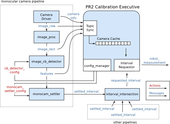
Each camera needs a processing pipeline to get the data into the executive, and finally into the calibration bagfile. The pipeline consists of the following:
Camera Driver - A source of images. Needs to produce raw images and camera_info. The PR2 uses wge100_camera
image_proc - Generates rectified images. See image_proc
image_cb_detector - Finds checkerboard corners based on a configuration received over an action. From image_cb_detector (unstable)
monocam_settler - Determines how long the checkerboard corners have been stationary in the image. From monocam_settler (unstable)

The cameras on the PR2 are defined in file cam_config.yaml
Example: narrow_left_rect:
cb_detector_config: /narrow_stereo/left/cb_detector_config
led_detector_config: /narrow_stereo/left/led_detector
settler_config: /narrow_stereo/left/monocam_settler_config
configs:
cb_7x6:
settler:
tolerance: 2.00
ignore_failures: True
max_step: 1.0
cache_size: 100
cb_detector:
active: True
num_x: 7
num_y: 6
width_scaling: 1
height_scaling: 1
subpixel_window: 4
subpixel_zero_zone: 1
led_detector:
active: False
cb_detector_config - Action namespace for reconfiguring checkerboard detector
led_detector_config - Action namespace for reconfiguring led detector (currently unused)
settler_config - Action namespace for reconfiguring the camera settler
Kinematic Chains
Each chain corresponds to a joint_states_settler that detects when the specified set of joints no longer is moving.
The chains on the PR2 are defined in chain_config.yaml
Example: left_arm_chain:
settler_config: /left_arm_chain/settler_config
configs:
tight_tol:
settler:
joint_names:
- l_shoulder_pan_joint
- l_shoulder_lift_joint
- l_upper_arm_roll_joint
- l_elbow_flex_joint
- l_forearm_roll_joint
- l_wrist_flex_joint
- l_wrist_roll_joint
tolerances:
- 0.002
- 0.002
- 0.002
- 0.002
- 0.002
- 0.002
- 0.002
max_step: 1.0
cache_size: 1500
Tilt Lasers
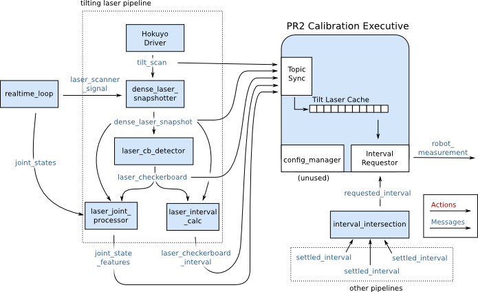
The tilt laser pipeline is definitely the most complex and confusing. This pipeline combines information from a laser scans and a control system to generate tilt, bearing, and range measurements to all of the corners on a checkerboard. The pipeline consists of the following:
Hokuyo Driver - This is what interfaces with the actual laser rangfinder hardware. The PR2 uses hokuyo_node
dense_laser_snapshotter - Combines the laser_scanner_signal from pr2_mechanism_controllers/LaserScannerTrajController with laser scans to generate a dense representation of a full laser scan. Uses pr2_dense_laser_snapshotter (no docs/unstable)
laser_cb_detector - Extracts checkerboard corners from an intensity image. Publishes the result in pixel space. Uses laser_cb_detector (no docs / unstable)
laser_joint_processor - Combines the detected corner locations, the original dense_laser_snapshot, and joint_states, and calculates the joint angles, bearings, and ranges that correspond to the detected corners in the intensity image. Uses laser_joint_processor (no docs / unstable)
laser_interval_calc - Uses the detected corner locations and dense_laser_snapshot to determine during what time interval the checkerboard was actually detected. We could simply use the time interval of the entire dense laser snapshot, but many times, this full interval is much longer than the time that the checkerboard was actually seen by the laser. Uses laser_interval_calc_node in laser_cb_detector (no docs / unstable)

Note that the laser_checkerboard_interval is not passed into interval_intersection. Instead, when a interval is requested, the tilt laser cache only returns measurements that occur completely within the requested interval.
Controllers
Each controller definition corresponds to a controller accepts trajectory_msgs/JointTrajectory messages. For the PR2, we rely on the JointSplineTrajectoryController: One for the head and one for each arm. The controller defintions are defined in controller_config.yaml.
Example:
head_traj_controller:
  topic: head_traj_controller/command
  joint_names:
  - head_pan_joint
  - head_tilt_joint
topic - ROS topic on which the controller is expecting commands
joint_names - Names of the joints that we'll be sending the controller commands for.
Defining Samples
When capturing data, the processing pipelines and controllers will definitely not be in the exact same configuration for every sample. Some cameras can be turned off, and the cameras that are turned on need to know what target they should be looking for. The controllers need to also be able to move the arms and head to a new location. Defining samples allows the user to reconfigure the processor pipeline and command the controllers for each view of the checkerboard.
The samples used to capture data on the PR2 are in pr2_calibration_launch/capture_data/samples_pr2_beta.


