| |
How to set up a Pilz PSENscan laser scanner with Ethernet
Description: Learn how to set up the PSENscan laser scanner with Ethernet for later use within the ROS environment.Keywords: Industrial, Ethernet, laser scanner, PSENscan, psen_scan, psen_scan_v2
Tutorial Level: BEGINNER
Next Tutorial: How to set up ROS to communicate with the scanner
Contents
WARNING
THE PILZ SOFTWARE IS PROVIDED AS-IS AND WITH NO WARRANTY (FOR MORE DETAILS SEE LICENSE).
System or plant integrators only
This tutorial is solely intended for system or plant integrators only. The system or plant integrator is responsible for taking into account the requirements from the respective current standard e.g. EN ISO 10218-2, EN ISO 61508 or taking equivalent measures.
Introduction
In this tutorial you learn how to set up the PSENscan laser scanner with Ethernet using the Pilz configuration tool, so that you are able to use the PSENscan laser scanner in a later step within the ROS environment.
Prerequisites
In order to complete this tutorial, you need the following:
- The operating manual. This tutorial does not replace the operating manual! Read it carefully first!
A Safety laser scanner PSENscan, list of ROS supported scanner models
A appropriate Ethernet cable and power cable for the PSENscan laser scanner have to be ordered separately. You can find the accesories for the laser scanner at the online shop. Select your laser scanner and click at Accesories.
- A 24V DC power supply.
- A PC with Windows 7, 10 or XP (32 Bit and 64 Bit) operating system and Ethernet interface.
The proper PSENscan Configurator software installed on the PC.
Setup connection between PSENscan and the PC
Connect the hardware
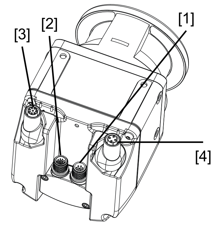
- Connect the power cable to [1] or [2] depending on the number of pins of your cable.
- Connect the power supply to the blue and brown wires of the power cable
- Connect the PC via Ethernet adapter cable to [4]
The power supply must not exceed 24V DC. See the appropriate operating manual for details on the wiring and pinouts.
- Connector [3] is not required here. This will be used to connect subscriber devices.
Search the network for the PSENscan laser scanner
Start the PSENscan Configurator on your PC and activate select Scanner → Search device in the upper menu bar to search the network for PSENscan laser scanners.
Connected devices of the PSENscan laser scanner are listed under Network environment.
Double-click the safety laser scanner from Network environment.
- The factory-set default IP address of the safety laser scanner: 192.168.0.10.
- The laser scanner and the host PC have to be in the same IP subnet.
- The IP address of the scanner can also be changed afterwards. See next chapter.
- The safety laser scanner is displayed in the work window with IP address, firmware version and status information.
Change the network IP address of the PSENscan laser scanner
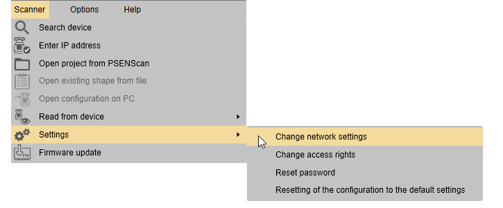
Select Settings → Change network settings.
- Enter the password for the safety laser scanner
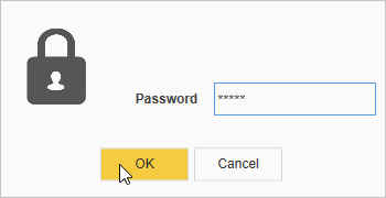
- You can find the password in the operating manual.
- Enter the network data for connecting to the network.
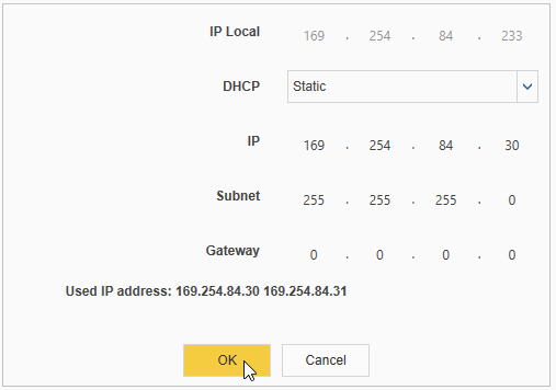
Click OK to continue.
- Finally the PSENscan safety laser scanner is displayed automatically with an updated IP address in the PSENscan Configurator.

- Alternatively you can change the IP address of your computer with the windows network settings.
Create a new configuration
To get raw non-safety-relevant scanner data in ROS, you still need to setup at least one safety zone. The safety configuration is not visible from ROS later on, but directly triggers the OSSD safety outputs of the scanner to stop motion.
- Click at the home button in the upper left corner.

Click on Create new configuration.

- Double click your product to proceed. You find the product id printed at side of the device.
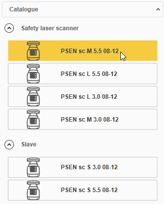
- Press the NEXT button on the upper right corner.

In the general properties tab choose the right number of pins for the power supply and evaluation device connection. It might be 8-pin or 12-pin. You can count the pins at your connector [2] or [1] as shown in Connect the hardware.
- Choose a name for your configuration.
- Press next until the configure zones dialog appears.
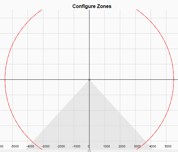
- Configure a smaller safety zone and a larger warning zone. Use the right mouse button on the coordinate system to choose between safety zone and warning zone.

- Click next and choose your scanner.
Press next until the Programming dialog appears and press the button Load.
After you pressed Load your configuration will be tested. There may occur several dialogs. Press OK on them until you are asked for a password. Use the same password like in the previous chapter.
Again answer the following dialogs with OK until the download dialog appears.

After the download is finished you will be asked for accepting or rejecting the new configuration. Press Accept button to proceed.
- The finish dialog appears. Wait until the scanner has rebooted.

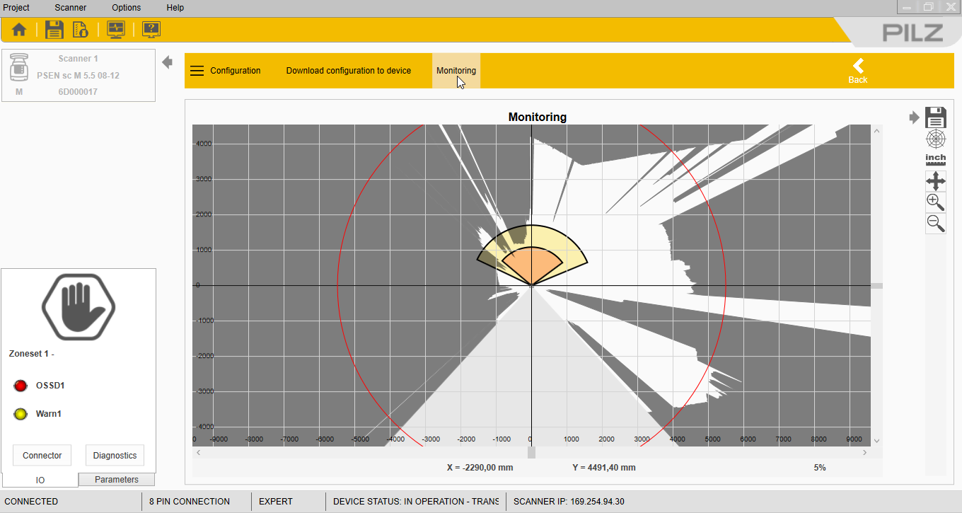
Press on Monitoring to display the 2d surroundings of the scanner.
How to proceed
From this point, you can connect your PSENscan to a machine running Linux and proceed with the ROS package setup.


