| Note: This tutorial assumes that you have completed the previous tutorials: This tutorial assumes you have successfully installed the SolidWorks to URDF Exporter. |
| |
Export a SolidWorks Assembly to URDF
Description: This tutorial covers the process of exporting a SolidWorks Assembly to URDF using the SolidWorks to URDF ExporterTutorial Level: BEGINNER
Next Tutorial: Organizing the SW assembly for a better workflow and export
Open your assembly in SolidWorks.
- Set the position of your joints as you would like them exported
Click "Tools>Export to URDF". If using 1.5.1 or older will be under "File>Export to URDF" (sometimes its "Extras>File>Export to URDF")
Property Manager
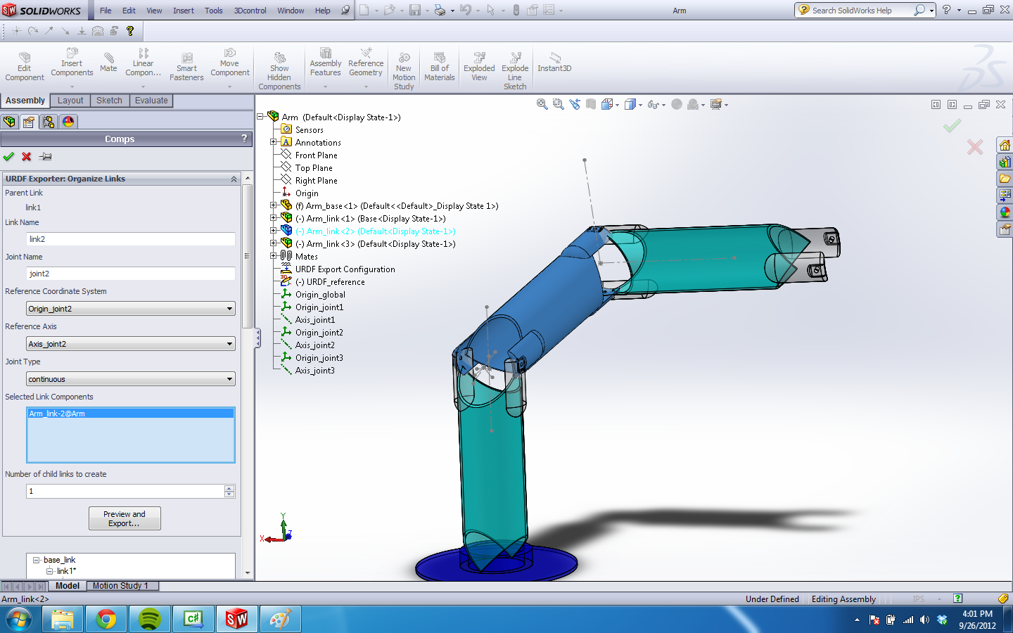
The exporter first brings up a property manager page for you to configure your URDF Export. You will need to configure each link and build the tree manually. After configuring this for the first time, the tool will save your configuration with the assembly itself. You should then be able to skip this step afterwards.

For each link, you need to give it a unique name, give it a unique joint name, select the components (assemblies or parts) in SolidWorks that are to be associated with that link and add the necessary number of children. If you have reference coordinate systems or axes you would rather the tool to use, you may select those from the list. You can also manually specify what each joint type is. Each URDF has only one base link. The joint configurations are disabled for this one link because there doesn't exist a joint to a higher level link. You only need to name the link (if you don't want to call it base_link), select its components and create its child links.
In SolidWorks, if you select components on the actual assembly display instead of the FeatureManager Design Tree, you will only be able to select parts. More likely you would rather select assemblies that represent the entire link, in which case you will have select them from the Design Tree as pictured above.
Note that for performance reasons, you can only select parts or subassemblies two levels deep into the SolidWorks model.

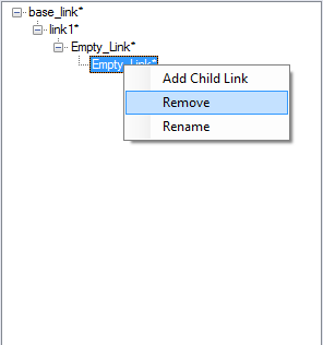
The configuration tree shows you all the links you've added. For each child link on the tree, a joint will be created to its parent link. You can select any link you've already added to change its properties. Right clicking a link will allow you to add children to or remove the link. You can also drag and drop links to re-order them. Dragging a parent link onto a child will cause the child link to switch positions with the parent link. The parent link's other children still stay with the original parent link.
Clicking the green check mark will just save your configuration and exit. Clicking the red x will allow you to exit without saving changes made to your configuration.
When you are ready to build your URDF, click "Preview and Export...". If you have specified the tool to automatically generate coordinate systems or axes, it will build them at this stage.
Joint Properties
Should you find that these joint origins are often not created in the most desirable location, you can change the reference coordinate systems and axes to suit your needs outside of the exporter. However, the model will work fine built as-is. The 3D Sketch is just used for temporary construction, but you may find it useful for adjusting the locations of the reference geometry. Pressing cancel on the Joint Properties page will allow you to save the names of the coordinate systems and axes to your configuration. You may then proceed to adjust the coordinate systems and axes. Restart the export process by clicking "File>Export to URDF". Ensure that the right names of coordinate systems and axes are saved for each link. The tool will no longer build them and instead refer to the reference geometry already in place.

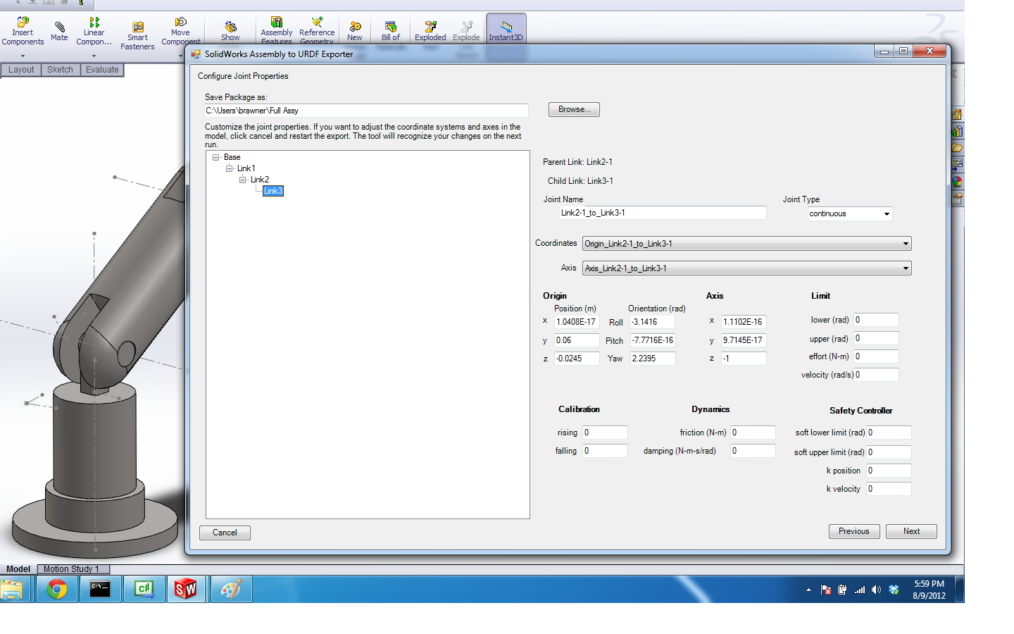
The joint page includes a non-configurable joint tree, where clicking each joint will bring up its properties on the right-hand side. You can customize the properties of any joint before exporting. These properties will not be saved however with the configuration. They will need to be re-entered each time.
Fields that are initially blank are not required by the urdf specifications. If they are left blank they will not be written to the URDF file. If you change a property of a section that includes other required fields, but neglect to specify them, they will be filled in with 0.
Click next to go to the Link Properties page
Link Properties
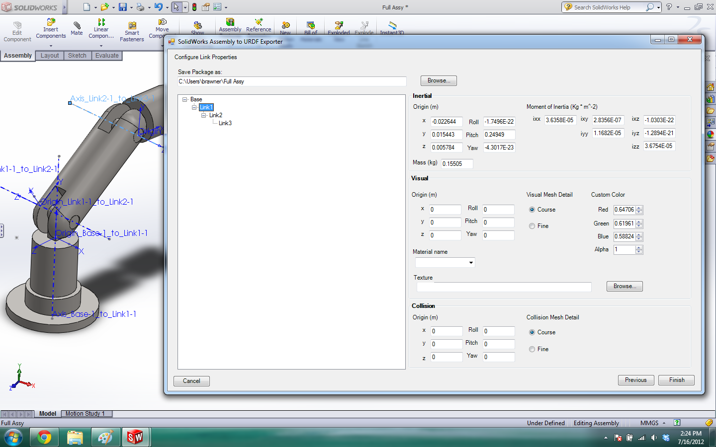
This page presents a similar view to the Part Exporter discussed earlier. You can change the link properties of any link in your tree. You can add a texture, change the color, change the origins of different sections, change the moment of inertia tensor, mass, etc. These changes will also not be saved with your configuration.

Click Finish to create your URDF package
The built package
The package will contain directories for meshes, textures and robots. It will also contain a ROS package.xml (manifest) file so you can use this as a ROS package by just copying it to your ROS system. The path locations in the URDF are relative to the package itself. If you do not have rospack, you will need to change the paths manually so that they refer to locations on the machine using the URDF files. If you do use rospack, you will need to add the package to a location in your $ROS_PACKAGE_PATH. If you find that your meshes are too complicated you can refer to the tutorial for improving complicated assembly exports or you can simplify complicated meshes by using a program like MeshLab or Blender.


