| Note: This tutorial assumes that you have completed the previous tutorials: Set up and test Optimization, Obstacle Avoidance and Robot Footprint Model. |
| |
Planning for car-like robots
Description: In this tutorial you will learn how to set up the planner for car-like robots (experimental).Keywords: Trajectory Optimization Local Planner Navigation Car-like Ackermann
Tutorial Level: INTERMEDIATE
Next Tutorial: Planning for holonomic robots
Planning and navigation of car-like robots is not intended explicitly by the navigation stack. However, the teb_local_planner tries to overcome this limitation by providing local plans that are feasible for ackermann drives. This is accomplished by extending the non-holonomic constraint by a minimum bound on the turning radius resp. by satisfying v/omega > r_min.
The teb_local_planner must indeed adhere to the specifications of the navigation stack by means of providing a geometry_msgs/Twist message containing translational and angular velocity v and omega respectively for commanding the robot rather than providing a ackermann_msgs/AckermannDriveStamped message. Refer to section Command interfaces for more details.
The minimum turning radius is set by the ros parameter ~<name>/min_turning_radius (see Node-Api). You might set the value slighly larger, since bounding is performed using soft-constraints in optimization (penalties).
Notice, backup/escape behaviors provided by the navigation stack must be turned off or replaced, since they do not support car-like robots.
The ability to drive backwards is required for the car-like robot setup. Thus, parameter ~<name>/weight_kinematics_forward_drive is ignored if the minimum turning radius is non-zero.
Supporting car-like robots / ackermann drives is still experimental. Please share thoughts, feedback, issues or code with the maintainer or start an issue on github.
Inspect optimized trajectories
Before setting up your robot for navigation, you might want to try and see how the planner optimizes trajectories for car-like robots. Repeat the optimization tutorial Setup and test Optimization and adjust the parameter ~<name>/min_turning_radius with rqt_reconfigure. See what's happening.
Otherwise you might want to watch the following video showing some examples:
Command interfaces
This tutorial distinguishes between different types of interfaces to communicate with the robot hardware node.
Translational and angular velocities
This kind of hardware driver accepts translational and angular velocities of the robot. In case of front-wheeled drives velocities are usually defined at the center of the rear axle. For this type, the published geometry_msgs/Twist message can be used directly.
Translational velocity and steering angle
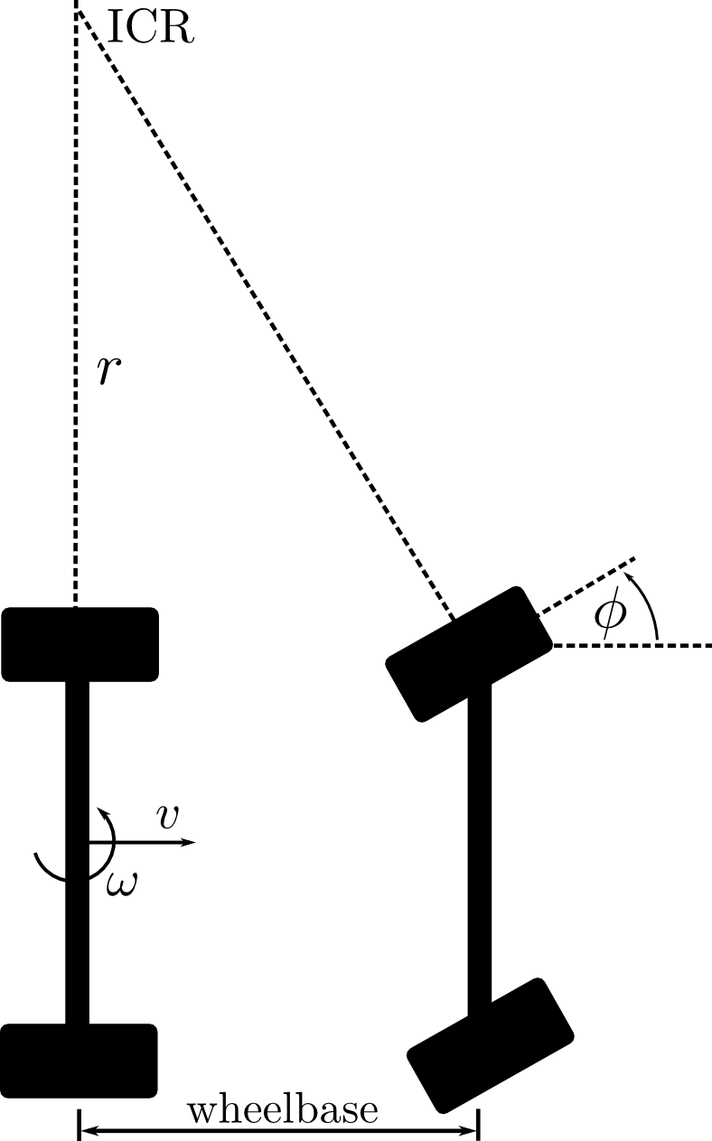
The relevant variables including the translational velocity v and the steering angle phi are illustrated in the following figure. ICR denotes the instant centre of rotation.

For a vanishing angular velocity omega=0 the turning radius r tends to infinity which in turn leads to a zero steering angle phi=0. Otherwise the turning radius r might be computed by v/omega. Then, the steering angle is derived by phi=atan(wheelbase/r) (which indeed includes the first case). Note, the steering angle is not defined for v=0 using the equation introduced above. One could use the last known valid steering angle. However, in the following we assume that for a vanishing translational velocity the (desired) steering angle is set to zero.
Twist message
Some command interfaces (such as the stage simulator in car-like mode) require a geometry_msgs/Twist, but with changed semantics. The angular velocity (z-axis) is interpreted as steering angle. Note, changing the semantics of a message is not preferred in general, better switch to the ackermann_msgs interface if possible.
The computation mentioned above can be performed automatically by teb_local_planner such that the angular velocity is substituted by the steering angle. Just set the parameter ~<name>/cmd_angle_instead_rotvel to true and specify the wheelbase ~<name>/wheelbase in meters. You might set the value to a negative value for rear-wheeled robots (but this is untested currently!).
Ackermann message
In case the robot hardware node accepts an ackermann_msgs/AckermannDriveStamped message provided by the ackermann_msgs package, velocity commands must be converted.
A possible approach is to add a small converter script/node that converts geometry_msgs/Twist to the desired type.
The following snippet converts the translational and angular velocities obtained from the planner to the new type.
   1 #!/usr/bin/env python
   2
   3 import rospy, math
   4 from geometry_msgs.msg import Twist
   5 from ackermann_msgs.msg import AckermannDriveStamped
   6
   7 def convert_trans_rot_vel_to_steering_angle(v, omega, wheelbase):
   8   if omega == 0 or v == 0:
   9     return 0
  10
  11   radius = v / omega
  12   return math.atan(wheelbase / radius)
  13
  14
  15 def cmd_callback(data):
  16   global wheelbase
  17   global ackermann_cmd_topic
  18   global frame_id
  19   global pub
  20
  21   v = data.linear.x
  22   steering = convert_trans_rot_vel_to_steering_angle(v, data.angular.z, wheelbase)
  23
  24   msg = AckermannDriveStamped()
  25   msg.header.stamp = rospy.Time.now()
  26   msg.header.frame_id = frame_id
  27   msg.drive.steering_angle = steering
  28   msg.drive.speed = v
  29
  30   pub.publish(msg)
  31
  32
  33 if __name__ == '__main__':
  34   try:
  35
  36     rospy.init_node('cmd_vel_to_ackermann_drive')
  37
  38     twist_cmd_topic = rospy.get_param('~twist_cmd_topic', '/cmd_vel')
  39     ackermann_cmd_topic = rospy.get_param('~ackermann_cmd_topic', '/ackermann_cmd')
  40     wheelbase = rospy.get_param('~wheelbase', 1.0)
  41     frame_id = rospy.get_param('~frame_id', 'odom')
  42
  43     rospy.Subscriber(twist_cmd_topic, Twist, cmd_callback, queue_size=1)
  44     pub = rospy.Publisher(ackermann_cmd_topic, AckermannDriveStamped, queue_size=1)
  45
  46     rospy.loginfo("Node 'cmd_vel_to_ackermann_drive' started.\nListening to %s, publishing to %s. Frame id: %s, wheelbase: %f", "/cmd_vel", ackermann_cmd_topic, frame_id, wheelbase)
  47
  48     rospy.spin()
  49
  50   except rospy.ROSInterruptException:
  51     pass
The script is also part of the teb_local_planner_tutorials package (ros parameters might be changed using a launch file):
rosrun teb_local_planner_tutorials cmd_vel_to_ackermann_drive.py
Robot Footprint Model
Car-like robots often constitute a non-circular shape/contour. Hence you might want to check out the tutorial Obstacle Avoidance and Robot Footprint Model carefully.
Example Setup
You can find an example setup with the stage simulator in the teb_local_planner_tutorials package.
Install the teb_local_planner_tutorials package
- Inspect the parameter/config files
Launch the carlike setup: roslaunch teb_local_planner_tutorials robot_carlike_in_stage.launch
Modify parameters using rosrun rqt_reconfigure rqt_reconfigure or by adapting the files.


