| Note: This tutorial assumes that you have completed the previous tutorials: TurtleBot Bringup, PC Bringup, Network Configuration. |
| |
3D Visualisation
Description: Visualising 3d and camera data from the kinect/asus.Keywords: turtlebot kinect asus
Tutorial Level: BEGINNER
Contents
Preparation
Make sure the minimal software has already been launched on the robot and you have configured your network correctly. Source your setup.bash.
Plug in your kinect xbox or asux xtion pro 3d sensor to the netbook.
Warning: Make sure that the 3d sensor has not been plugged into a usb 3.0 port (these are usually, but not always coloured blue) since kinect xbox and asus xtion pro devices only work for 2.0. |
Starting the 3D sensor
Make sure the minimal software has already been launched on the robot and you have configured your network correctly.
roslaunch turtlebot_bringup 3dsensor.launch
Note that Xtion as a sensor. If your robot uses Kinect, please follow the Kinect Setup before start your 3d sensor.
By default, this will launch the 3d sensor with all the processing modules ON. You can turn these off by sending the appropriate arguments to the launch command (look inside 3dsensor.launch for more information).
The turtlebot apps themselves do this - they only enable exactly what they need to minimise the amount of processing that is done for their task.
On the PC
Start rviz already configured to visualize the robot and its sensor's output:
> roslaunch turtlebot_rviz_launchers view_robot.launch
Note that this also lets you various other aspects of the robot as well.
Enable the desired displays
To visualize any display you want, just click on its check button. These are the displayed sensors:
DepthCloud
Registered DepthCloud
- Image
PointCloud
Registered PointCloud
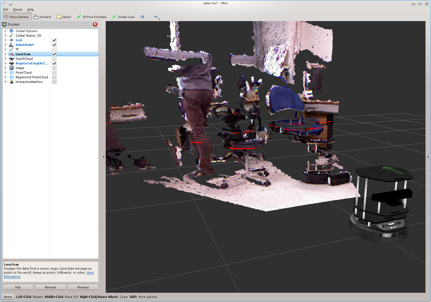
For example, in the following screen capture both LaserScan and Registered DepthCloud are enabled.

A bit more about 3D data structures
Groovy introduced the depth_image data type that is now used by default in most places. Without processing, the openni nodelet will just produce depth images. This is the raw data structure provided by the openni driver for 3d information. Upon enabling some processing, this can be converted into the more usable PCL format.
RViz now has views for both data types and you'll note the visualisation of both data types is the same - a 3d point cloud drawn by opengl. You can see both plugins when running rviz via view_robot.launch.
Q) How are depth images and point clouds used in the Turtlebot?
For low level operations - depth images are used. Since no conversion is done, it's faster. The depthimage_to_laserscan package does this because it needs to be fast to save computation for mapping. For more complicated operations, such as turtlebot_follower it uses the pcl format where it then has access to the host of algorithms in the point cloud library.
The default 3dsensor.launch file configures the 3D sensor to provide you with fully processed 3d data (registrations, point clouds, fake laser scans) for convenience. The turtlebot apps like follower each call 3dsensor.launch and enable only the processing modules they need via clever use of roslaunch args.
Q) I can't visualise DetphCloud and PointCloud
Note that the Depth registration option for TurtleBot is true by default. It enables Registered DepthCloud and Registered PointCloud which provides coloured point clouds for convenience. It is configurable not to use depth_registration as false for advanced users like turtlebot_follower
What Next?
Keyboard Teleoperation or return to TurtleBot main page.


